Method for guiding an electromagnetic radiation, in particular in an integrated optical device

a technology of electromagnetic radiation and optical device, applied in the direction of optical waveguide light guide, instrumentation, nanotechnology, etc., can solve the problem that the application of photon focusing in integrated optics is limited

Inactive Publication Date: 2007-06-19
GOOGLE LLC
View PDF12 Cites 30 Cited by
  • Summary
  • Abstract
  • Description
  • Claims
  • Application Information

AI Technical Summary

Benefits of technology

[0019]The Applicant has found that, by opportunely choosing the geometrical and physical characteristics of a photonic crystal and the wavelength of an electromagnetic radiation to be transmitted therein, it is possible to achieve a particular propagation condition, herein below referred to as “photon guiding”, wherein a beam of light can be propagated substantially collimated in a region of the crystal of regular periodicity. More specifically, due to the particular conditions “observed” by a beam of light propagating in a photonic crystal designed according to the present invention, the beam self-collimates during propagation.

Problems solved by technology

The Applicant observes that, besides having being studied only at theoretical level, applications of photon focusing would be of limited use in integrated optics.

Method used


Image

  • Method for guiding an electromagnetic radiation, in particular in an integrated optical device
  • Method for guiding an electromagnetic radiation, in particular in an integrated optical device
  • Method for guiding an electromagnetic radiation, in particular in an integrated optical device

Examples


example 1

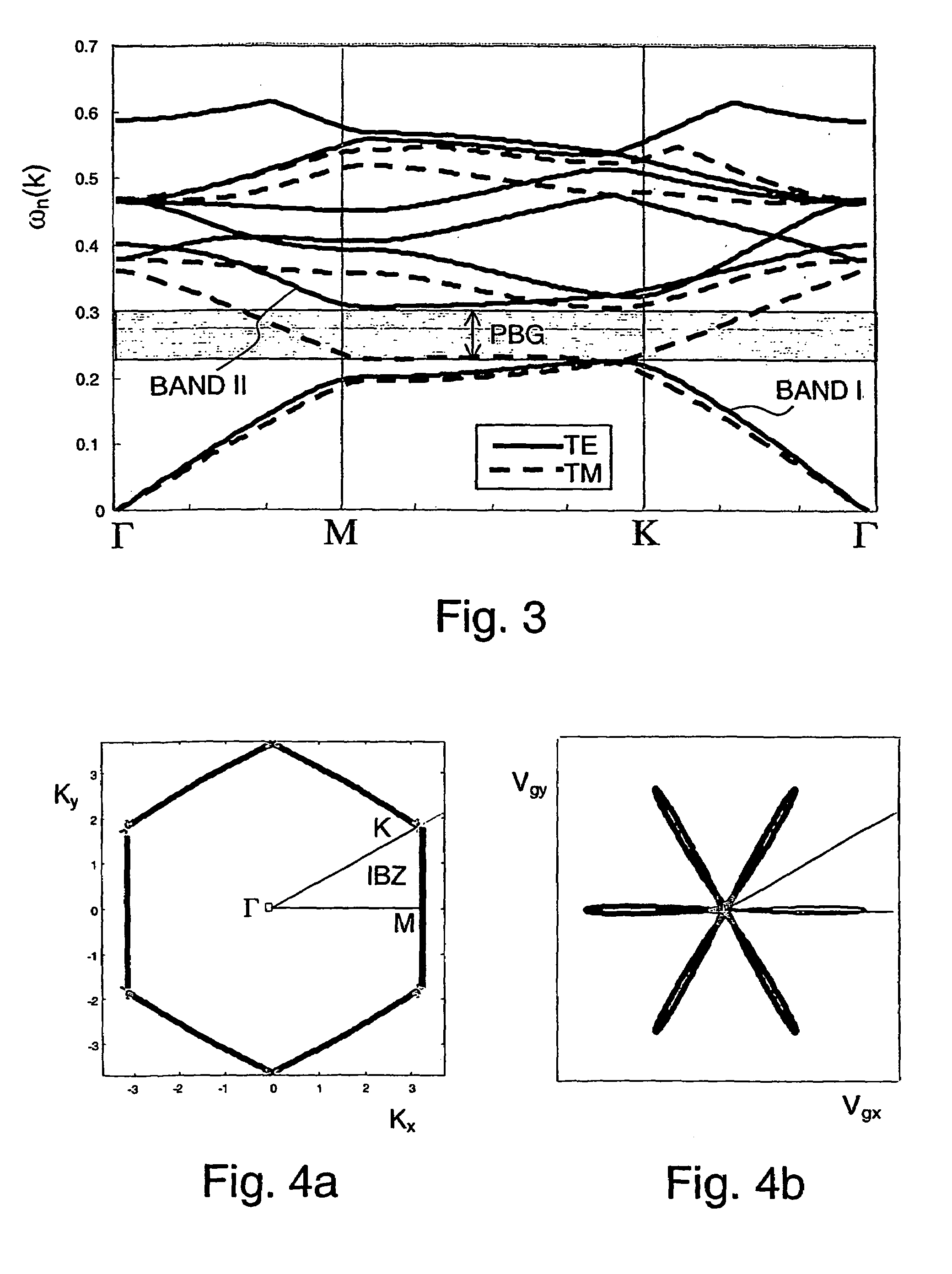
[0123]In a first set of simulations, it is shown how the characteristics parameters R, n and ωn can be selected for achieving photon guiding. The simulation model previously described has been used for determining the group velocity distributions for different combination of values of said parameters. A photonic crystal having a (equilateral) triangular array of air holes and an initial isotropic distribution of the group velocities has been considered. The analysis is limited to the first dispersion band of the mode TE and it is performed by expressing the group velocity in polar coordinates.

[0124]A isotropic distribution of group velocities about a predetermined crystal axis in an angular range of π / 3 for a triangular array, and of π / 2 for a square array, has been considered.

[0125]The parameter R has been varied between 0.15 and 0.45 by steps of 0.3; as concern the parameter n, the values 1.5, 2, 2.5, 3.25 and 3.5 have been considered; the parameter ωn has been varied of steps of ...

example 2

[0143]The same simulation has been performed for a photonic crystal having a square array of holes. Differently from above, the percentage of points originally in a range of π / 2 about the considered propagation direction that have been concentrated within an angular range of π / 6 is now considered. The parameters R and n have been varied between 0.15 and 0.45 and between 2 and 3.5, respectively. Table VI reports the results of this simulation. In particular, Table VI shows, for each possible combination of values of the parameters R, n, the value of ωn that allows maximizing the guiding effect.

[0144]

TABLE VI

[0145]As above, areas corresponding to a possible condition and a more preferred condition for photon guiding have been delimited by a heavy line and a thin line, respectively.

example 3

[0146]X-crossing without cross-talk in a photonic crystal according to the present invention has been demonstrated by a numeric simulation.

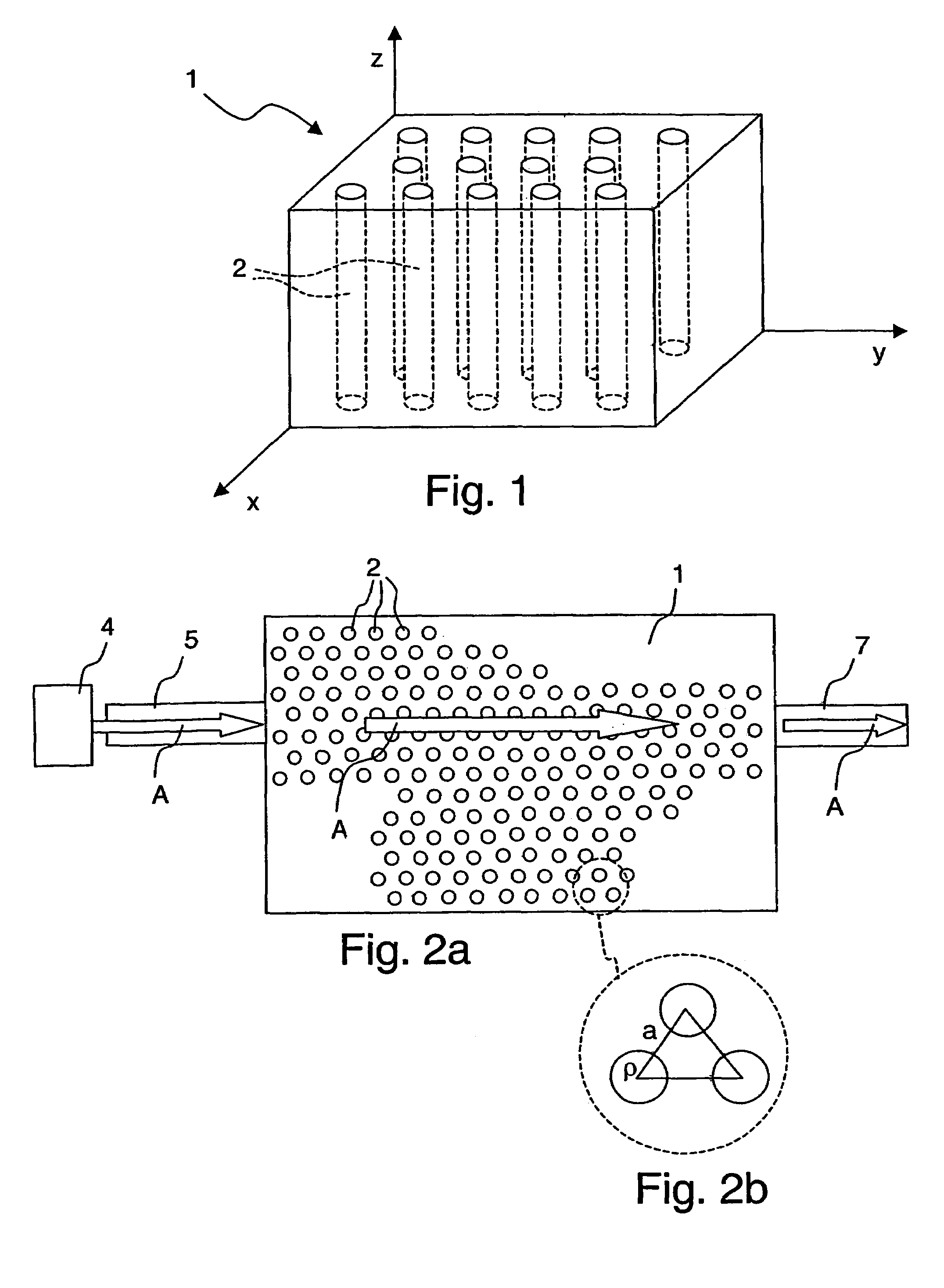
[0147]The simulation has been performed by considering a triangular array of holes filled with air, with a period a of 0.372 μm. The bulk refractive index n is 3.5, the normalized spacing R is 0.42 and the normalized frequency ωn is 0.24. Two beams of light A, B at wavelengths 1550 nm, having a width of about 5 μm are propagated at 60° from each other along two crystal axes. Only the mode TM is considered. Propagation is simulated in a plane x–y, with input of light at y=0 μm. FIG. 11 shows the propagation of the two beams A, B within the photonic crystal. It can be appreciated that the beams cross each other and no alteration occurs after having left the interaction region (i.e., without cross-talk).


PUM


Abstract

A method for guiding electromagnetic radiation by providing a photonic crystal made of a bulk material with a predetermined refractive index and having a periodic array of holes with predetermined radius, and feeding to that region an electromagnetic radiation having a wavelength in the fundamental photonic band and so related to the refractive index of the bulk material, to the radius of the holes and to the period of the array that, starting from an isotropic distribution of the wave vectors within a first angular range that is twice the angular extension of the first irreducible Brillouin zone of the photonic crystal, the corresponding group velocity vectors are rearranged as concerns direction and module so that at least 50% of them become directed within a second angular range that is about one-third of the first angular range and the width at half-maximum of the distribution of the modules of the vectors is lower than about two-thirds of the second angular range.

Description

CROSS REFERENCE TO RELATED APPLICATION[0001]This application is a national phase application based on PCT / EP02 / 02466, filed Mar. 6, 2002, the content of which is incorporated herein by reference.BACKGROUND OF THE INVENTION[0002]1. Field of the Invention[0003]The present invention relates to a method for guiding an electromagnetic radiation, in particular in an integrated optical device for optical telecommunications.[0004]2. Description of the Related Art[0005]In optical telecommunication systems, information is typically coded in short optical pulses by suitable optical sources, such as light-emitting diodes (LEDs) or semiconductor lasers, which pulses are transmitted along an optical-fibre network and received by photodetectors. Many different signals can be transmitted using a single wavelength of light by interweaving the pulses from different sources, a technique known as time-division multiplexing (TDM).[0006]A simple way of increasing the amount of data that can be transmitte...

Claims


Application Information

Patent Timeline
Patent Type & Authority Patents(United States)
IPC IPC(8): G02B6/26G02B6/12G02B1/02G02B6/122G02B6/125
CPCB82Y20/00G02B6/1225G02B6/125
Inventor ROMAGNOLI, MARCOTORMEN, MAURIZIOBONATI, CAMILLA
Owner GOOGLE LLC
Why Eureka
Try Eureka