Dynamic dew point analysis method and a device for determining the dew point temperature and relative humidity

a technology of dynamic dew point and analysis method, which is applied in the direction of measuring devices, scientific instruments, instruments, etc., can solve the problems of rain and other problems, and achieve the effect of low thermal conductivity and very accurate determination of temperature changes

Inactive Publication Date: 2007-06-26
AALBORG UNIV
View PDF13 Cites 10 Cited by
  • Summary
  • Abstract
  • Description
  • Claims
  • Application Information

AI Technical Summary

Benefits of technology

[0018]In a further advantageous embodiment the thermocouples are arranged in a member exhibiting low thermal conductivity such as a plastic member so that only the tips of the thermocouples are exposed to the measuring chamber of which one thermocouple is shielded. The member constitutes an isolating member so that the thermocouples are isolated from a source of heat or cooling which could otherwise influence the measurements. By only exposing the tips of the thermocouples, which can have a very limited area, for example 0.25 mm2, it is possible to determine the temperature change very accurately. As one thermocouple is shielded, for example by covering the tip of the thermocouple with a cap, and not covering the other thermocouple, the conditions surrounding the thermocouples are basically equal, so it will be assured that only the condensation and the change in temperature on one thermocouple are the phenomena which are actually measured by the two thermocouples.
[0019]In a further advantageous embodiment of

Problems solved by technology

A reading of a 100% relative humidity means that the air is totally saturated with

Method used


Image

  • Dynamic dew point analysis method and a device for determining the dew point temperature and relative humidity
  • Dynamic dew point analysis method and a device for determining the dew point temperature and relative humidity
  • Dynamic dew point analysis method and a device for determining the dew point temperature and relative humidity

Examples


Embodiment Construction

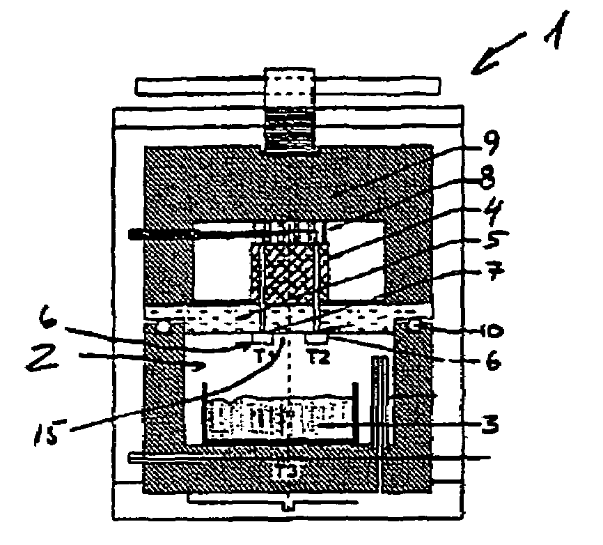
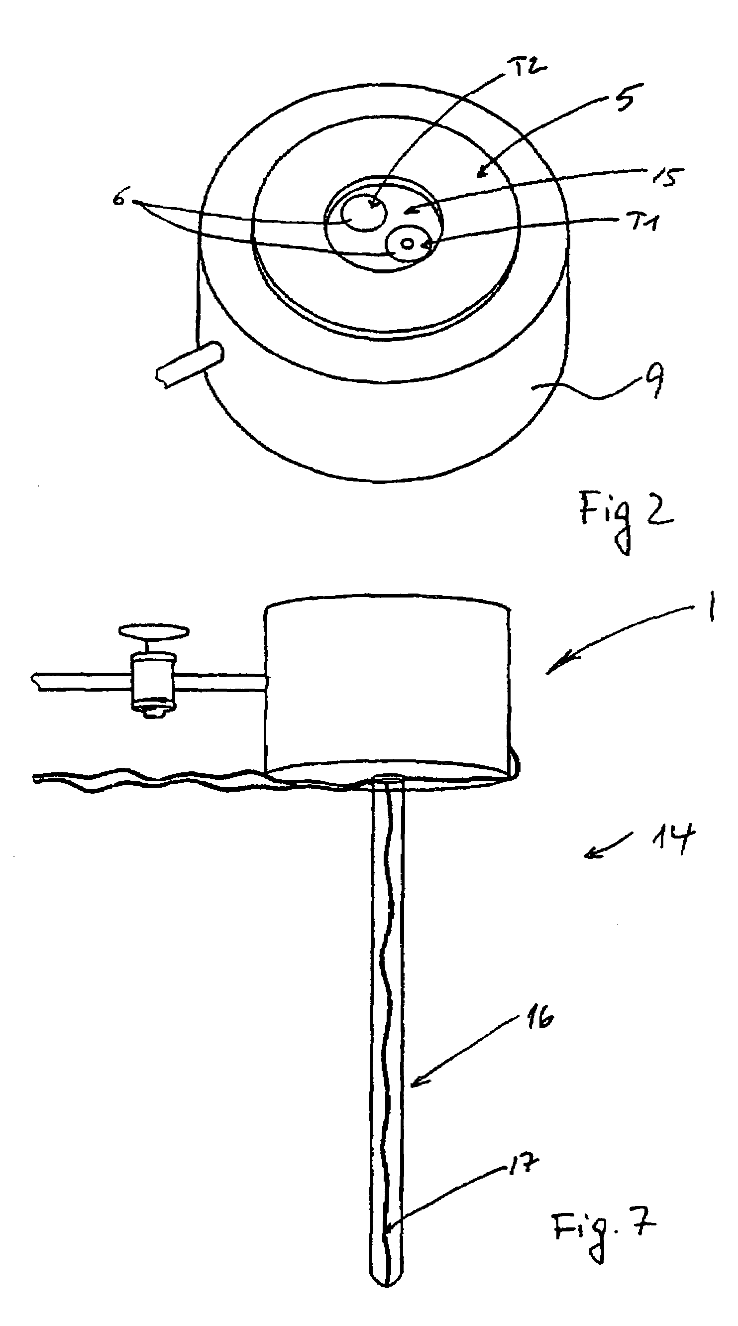
[0037]A schematic cross section of the dew point meter 1 is shown in FIG. 1, and the dew point meter is shown in FIG. 2 together with details of the sensor surface.

[0038]The illustrated dew point meter comprises an outer casing 9 made from for example aluminium. The casing is in two parts and a seal 10 is fitted in the connecting section of the casing 9. The measuring chamber 2 arranged inside the device 1 contains the sample 3 to be tested. The measuring chamber 2 is evacuated so that the atmosphere is pure water vapour in equilibrium with the sample.

[0039]The bottom side of the sensor unit is equipped with two type-T thermocouples (copper / constantan), marked T1 and T2, respectively. The location of these thermocouples is shown in detail in FIG. 1. The thermocouples are electrically isolated from, but in intimate thermal contact with, a copper block 4. The thermocouples extending from the copper block 4 are embedded in a thermoset plastic element 5. The thermocouples are composed o...


PUM


Abstract

The invention provides for a dynamic dew point analysis method as well as an apparatus for carrying out the method wherein the method comprises: arranging a moisture containing gas in the immediate vicinity of at least two thermocouples, where one thermocouple is shielded from the gas; creating an analogous temperature change in both thermocouples and registering the temperature in both thermocouples during a cycle where the condensation point of the moisture containing gas is passed, using the different temperatures from the at least two thermocouples as input for determining the dew point according to basic thermodynamic principles.

Description

[0001]This application claims the benefit of Danish Application No. 2001 01725 filed Nov. 20, 2001 and PCT / DK02 / 00773 filed Nov. 18, 2002.BACKGROUND OF THE INVENTION[0002]The present invention relates to a dynamic dew point analysis method as well as a device for determining the dew point temperature and relative humidity.[0003]In the art a number of different methods and devices have been suggested in order to determine the relative humidity as well as the dew point temperature. Among these is for example an optical system arranged in connection with a mirror or other reflective surface. By projecting a light beam and measuring the reflection from the light-reflecting surface the time when the light reflection diminishes due to condensation on the light-reflecting surface can be determined and the temperature corresponding to that time / instant is recorded whereby the dew point temperature has been determined. With this temperature the relative humidity in the vicinity of the reflec...

Claims


Application Information

Patent Timeline
IPC IPC(8): G01N25/02G01N25/64G01N25/68
CPCG01N25/64G01N25/68
Inventor JENSEN, OLE MEJLHEDEHANSEN, LEGAL REPRESENTATIVE, KIRSTEN HOJSTHANSEN, DECEASED, PER FREIESLEBEN
Owner AALBORG UNIV
Why Eureka
Try Eureka