Method and a system for programming an industrial robot

a robot and industrial technology, applied in the field of industrial robot programming, can solve problems such as inefficiency of robots, and achieve the effect of reducing the teaching time of the teaching process and increasing the quality of processing results

Active Publication Date: 2007-06-26
ABB (SCHWEIZ) AG
View PDF18 Cites 53 Cited by
  • Summary
  • Abstract
  • Description
  • Claims
  • Application Information

AI Technical Summary

Benefits of technology

[0010]The object of the present invention is to provide an improved industrial robot programming solution, which reduces the teaching time for the teaching process and increases the quality of the processing result.
[0011]According to one aspect of the invention, the object is achieved by means of the initially defined method, comprising: obtaining information about the position of the waypoints in relation to the object, storing the information about the position of the waypoints, simulating the robot path based on the received information about the waypoints and a model of the robot, generating a graphical representation of the robot path based on the simulated robot path, and displaying a view comprising the object and said graphical representation of the robot path projected on the object. This method improves the teaching process by visualizing the robot path in relation to the real object to be processed.
[0012]Obviously, it is not efficient if the robot moves the tool in straight lines between the waypoints specified by the operator. In order to achieve an efficient robot program, effecting the tool to pass through the specified waypoint at required speed and direction, a robot path has to be generated. The robot path is generated from a path simulator, simulating the robot path based on specified waypoints and a model of the robot. Computer generated information, representing the generated robot path, is displayed projected on the real object or on an image of the real object. Thus, it is possible for the operator to get extended visual feedback while making a new robot program related to a specific object. It is no longer necessary to run the robot program to view the result of the programming. Thereby, the number of iterations needed and thus the teaching time is reduced. The method is particularly advantageously during off-line programming. Another advantage of the method is that no 3D CAD model of the object is needed, since the generated graphic is projected on the real object or on an image of the real object. The programming time will be significantly reduced since the operator will be able to make a robot program at a higher quality level during the first iteration compared to today's methods.
[0018]According to a further embodiment of the invention, the method comprises: obtaining information about which tool to be used to perform the process and about the orientation of the tool in the waypoints, simulating the tool performing the process, generating a graphical representation of the tool performing the process along the robot path based upon the obtained information about the position of the waypoints and the orientation of the tool, and displaying a view showing the tool moving along the robot path performing the process, based on the generated graphical representation of the simulation of the tool performing the process. For example, if the process is painting, a virtual paint-gun is displayed moving along the robot path performing the paint procedure and the paint being applied onto the object is shown. This visualization of the tool performing the process helps the operator to evaluate the taught robot program.
[0019]According to a further embodiment of the invention the view of the robot path and / or the result of the process is displayed as a function of time and the view is displayed proportional to the real-time. Real-time is the actual time it takes for the robot to move through the path performing the process. In a preferred embodiment the method further comprises: receiving information about a desired speed of the displaying of the view, and displaying the view in accordance with the desired speed. Preferably, the speed is altered in relation to the real-time. Sometimes the operator finds the real-time speed to be too fast, and thus wishes to slow down the speed. This embodiment of the invention makes it possible for the operator to alter the speed of the display.
[0021]According to a further embodiment of the invention the method comprises simulating the quality of the result of the process based on one or a plurality of predefined quality parameters and the model of the process, generating a graphical representation of the quality of the result of the process, and displaying the view based on the generated graphical representation of the simulation of the quality of the result of the process. Preferably, the method further comprises estimating whether the quality of the result does not meet one or several quality requirements, based on said simulation of the quality of the result of the process, and generating said graphical representation with a visual feedback to the operator where the process quality is estimated not to meet the quality requirements. In the paint process, the quality parameters for instance are overlap between paint strokes, parts of the object not covered by the paint, the paint thickness, the paint width, and sag of the paint. Thus, if the paint is estimated to be sagging or not covering the object, this will be shown by the generated graphics. This embodiment makes it possible for the operator to generate robot programs with high quality, without the need of executing the actual process.

Problems solved by technology

Obviously, it is not efficient if the robot moves the tool in straight lines between the waypoints specified by the operator.

Method used


Image

  • Method and a system for programming an industrial robot
  • Method and a system for programming an industrial robot
  • Method and a system for programming an industrial robot

Examples


Embodiment Construction

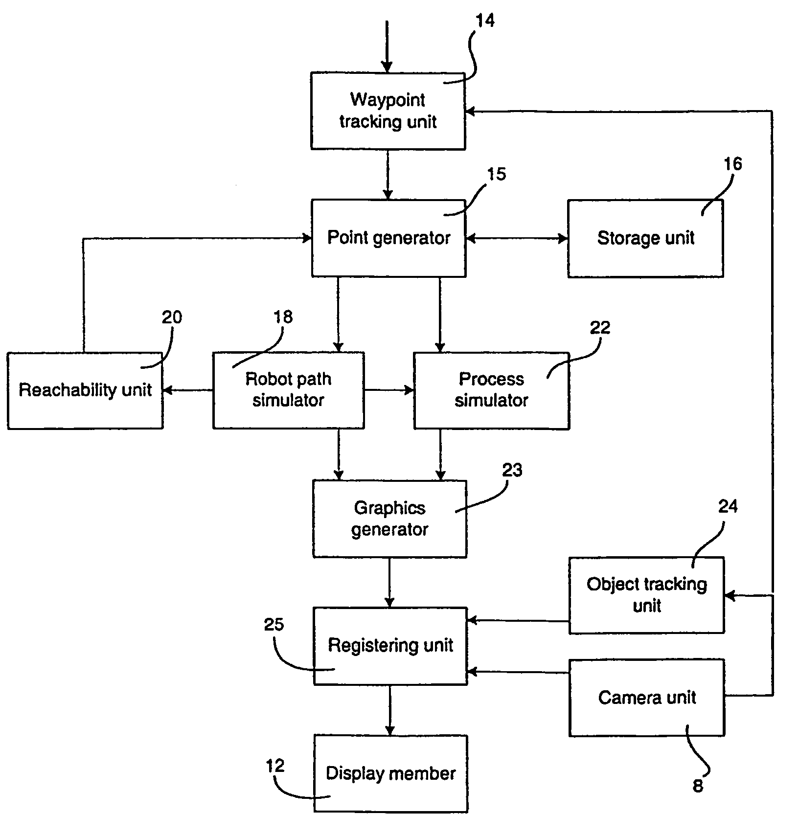
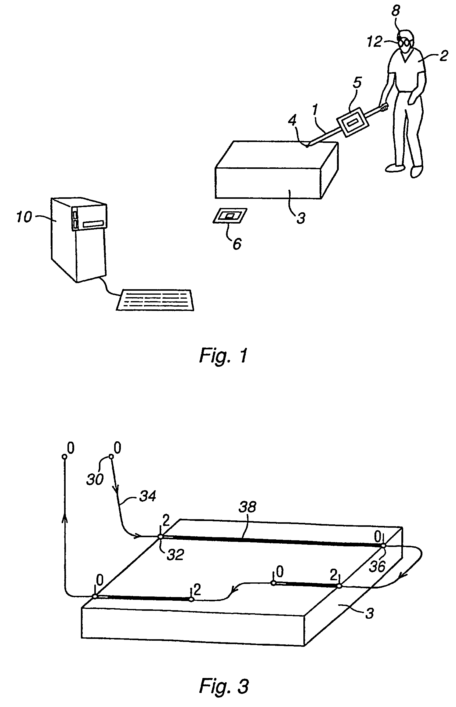
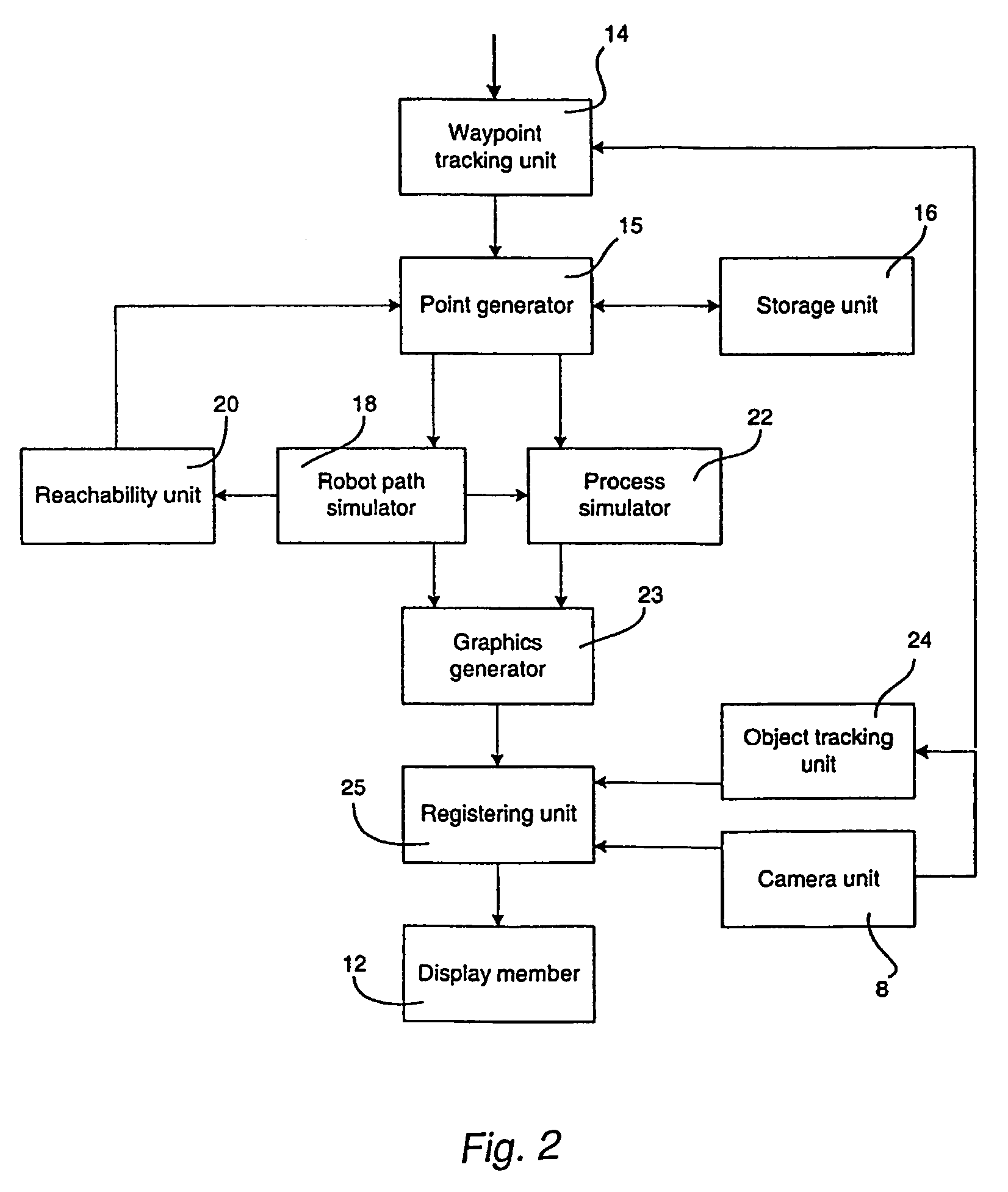
[0036]FIG. 1 illustrates a system for use in connection with programming of an industrial robot according to the present invention. The system comprises a pointing member 1 utilized by a human operator 2 for teaching the robot how to process an object 3. The pointing member can either be the processing tool itself, or a device particularly adapted for the purpose of teaching the processing of the object. The teaching comprises teaching a number of waypoints given in a specific sequence and located on or in the close vicinity of the object 3. Each waypoint comprises the position of a point on or in a close vicinity of the object, the orientation of a processing tool, such as a paintbrush, in the point, and data related to the process.

[0037]The operator holds the pointing member 1 in his hand and points at the point he wants to include in the path and orientates the pointing member as he wishes the processing tool to be oriented in the point. The operator records a point by activation...


PUM


Abstract

A method and a system for use in connection with programming of an industrial robot. The programming includes teaching the robot a path having a number of waypoints located on or in the vicinity of an object to be processed by the robot. The system includes elements for obtaining information about the waypoints of the path in relation to the object, a storage unit for storing the obtained information, a simulation unit for simulating the robot path based on the obtained information about the waypoints and a model of the robot, a graphics generator for generating a graphical representation of the simulated robot path, and a display member for displaying a view comprising the object and the graphical representation of the robot path projected on the object.

Description

FIELD OF THE INVENTION[0001]The present invention relates to a method in connection with programming of an industrial robot, comprising teaching the robot a path which has a number of waypoints located on or in the vicinity of an object to be processed by the robot. The processing of the object could be any type of surface processing application carried out by an industrial robot, such as painting, glazing, sanding, polishing, grinding, welding, picking and placing, and assembling.[0002]The present invention also relates to a computer program product directly loadable into the internal memory of a computer, comprising software code portions for performing the steps of the method according to the invention, when said product is run on a computer.[0003]The present invention also relates to a computer readable medium having a program recorded thereon, where the program is to make a computer perform the steps of the method according to the invention when said program is run on the compu...

Claims


Application Information

Patent Timeline
Patent Type & Authority Patents(United States)
IPC IPC(8): G05B19/04B25J9/16G05B19/42G06F19/00
CPCB25J9/1671G05B19/42G05B2219/35487G05B2219/35506G05B2219/36436G05B2219/39449G05B2219/40311G05B2219/40392G05B2219/40479
Inventor PRETLOVE, JOHNSKOURUP, CHARLOTTEPETTERSEN, THOMAS
Owner ABB (SCHWEIZ) AG
Why Eureka
Try Eureka