Aiding in a satellite positioning system

a satellite positioning system and satellite technology, applied in the direction of navigation instruments, instruments, broadcast with distribution, etc., can solve the problems of high cost of atomic clocks, inaccuracy of satellite positioning receiver measurement, and 8 satellite clock errors

Inactive Publication Date: 2007-06-26
CSR PLC
View PDF184 Cites 173 Cited by
  • Summary
  • Abstract
  • Description
  • Claims
  • Application Information

AI Technical Summary

Problems solved by technology

Although atomic clocks are very precise with a stability of about 1 to 2 parts in 1013 over a period of one day, a slight error (generally known as clock drift) may occur in the clocks over time resulting in satellite clock errors of about 8.64 to 17.28 ns per day with corresponding range errors of 2.59 to 5.18 meters.
Unfortunately, this approach assumes that the distances measured from the GPS receiver to the satellites are very accurate and there is no bias error.
Any errors in the synchronization between the clocks will cause inaccuracies the measurement of the location of the GPS receiver.
Atomic clocks, like those found in the GPS satellites, are very expensive typically costing a few thousand dollars for a Rubidium clock and a few tens of thousands of dollars for a Cesium clock.
They are therefore not practical for use in typical consumer GPS receivers.
However, unless the inaccuracy of the GPS-CLK is determined and corrected for, synchronization with that of the atomic clocks of the satellites will be partially off and the resulting distance measurement calculated by the GPS receiver will be partially inaccurate.
Thus, the error of the GPS-CLK is yet another unknown variable that must be determined to accurately determine the location of the GPS receiver.
Besides accuracy, another problem associated with the error of the GPS-CLK relative to the GPS satellite clocks is the resulting acquisition time for the GPS receiver commonly known as the time to first fix (TTFF).
Unfortunately, the GPS-CLK can have large frequency drift during the first couple minutes after being powered on.
The large frequency drift can cause significant degradation on TTFF performance and may even result in lack of navigation fix in weak signal environments.
Although there are a large number of GPS satellites positioned above the earth's atmosphere, it is not always possible for a GPS receiver to receive accurate transmissions from the required number of GPS satellites necessary to calculate the position of the GPS receiver.
Any number of problems may prevent a GPS receiver from receiving the necessary number of signals, or from receiving accurate signals because of transmission or receiver errors.
These problems can result in high TTFF times.
For example, a GPS receiver may not be able to receive the necessary number of GPS transmissions due to physical obstructions in the atmosphere or on the earth.
Alternatively, even though a GPS receiver may be able to receive the necessary signals, the signal could be inaccurate due to any of the following: (i) error in the satellite clock; (ii) error in the receiver clock; (iii) error in computed satellite position; (iv) atmospheric errors caused by the ionosphere or the troposphere; (v) multipath errors caused by the receipt of reflective signals; (vi) receiver measuring errors and / or (vii) selective errors, or man made errors.
This method, however, typically involves the use of additional complicated circuitry that first locks and / or calibrates the GPS-CLK to the precision carrier frequency and then maintains dynamic synchronization between the GPS-CLK and precision carrier frequency.

Method used


Image

  • Aiding in a satellite positioning system
  • Aiding in a satellite positioning system
  • Aiding in a satellite positioning system

Examples


Embodiment Construction

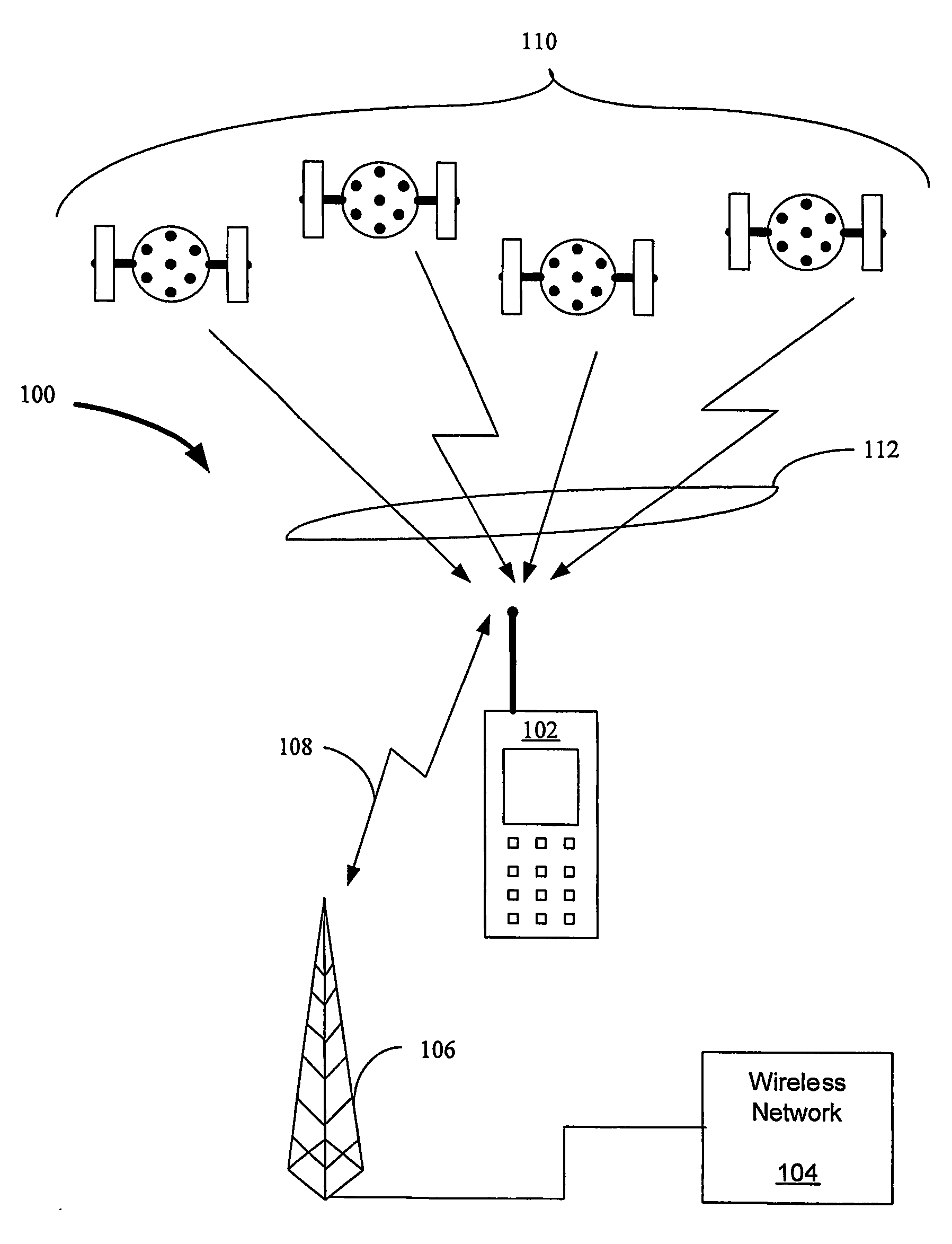
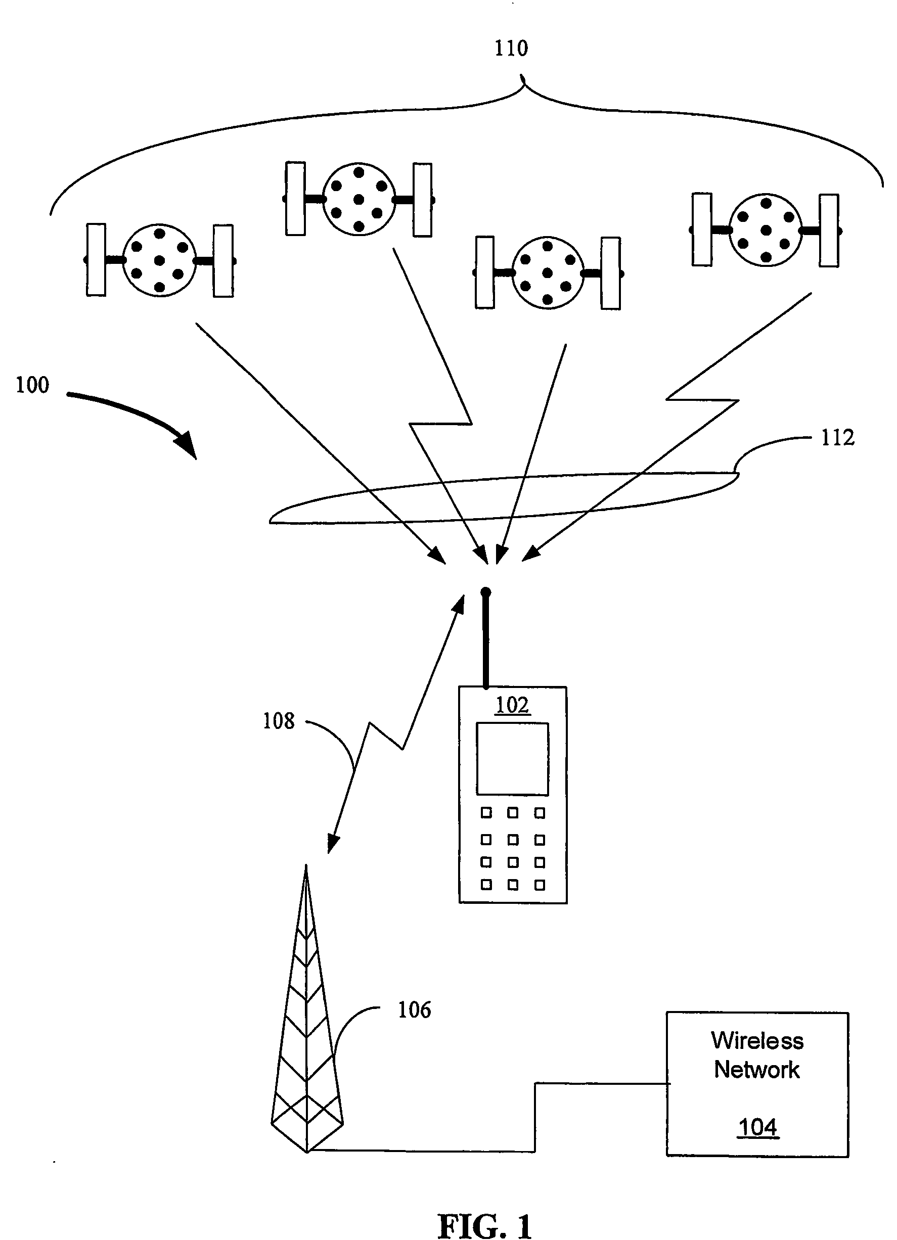
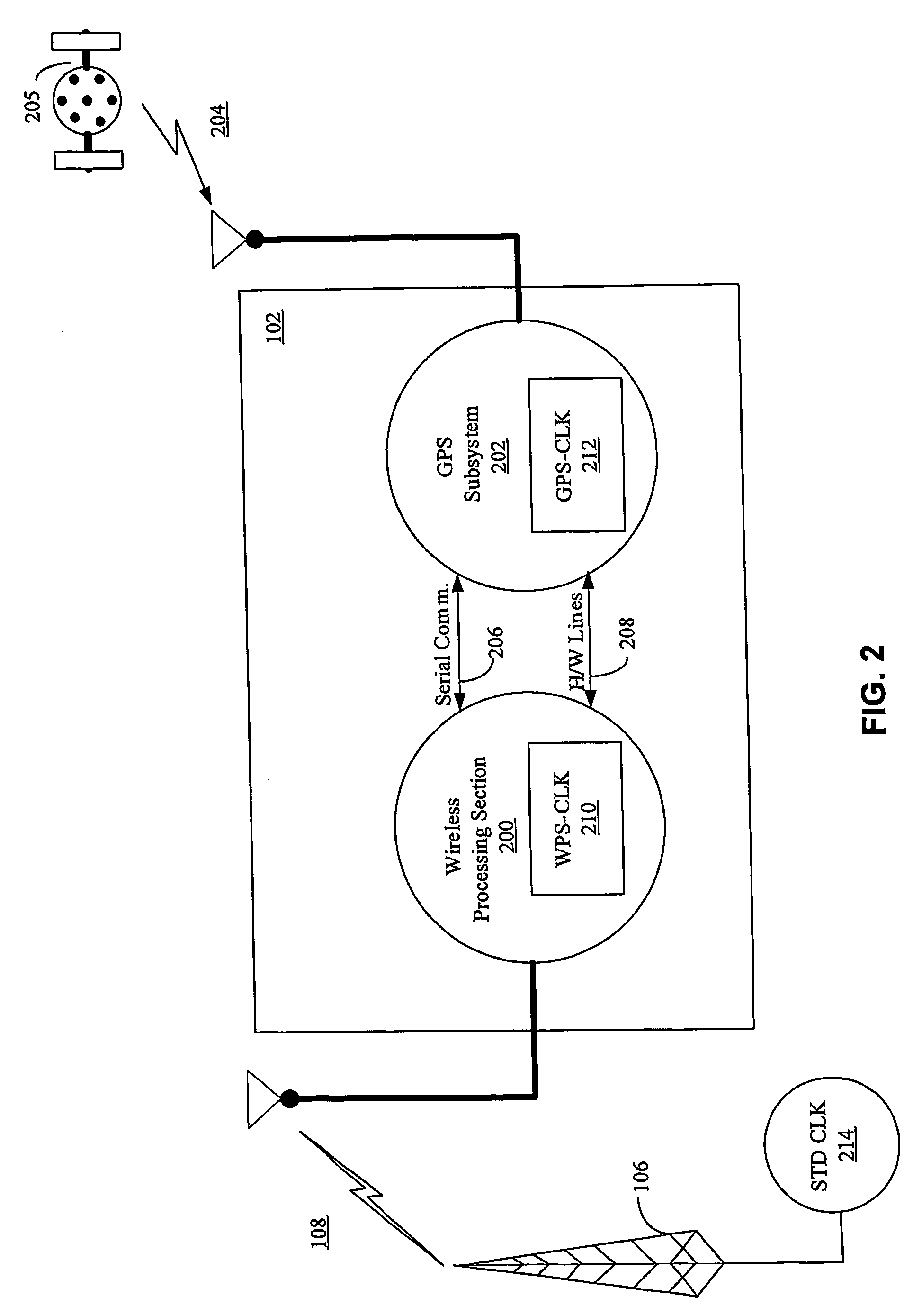
[0037]FIG. 1 is an example implementation of a GPS system 100 using a wireless device 102 having a GPS receiver (not shown) located within the wireless device 102. As shown in FIG. 1, during operation, the wireless device 102 is in signal communication with a wireless network 104 via a basestation 106 and wireless transmission path 108 and is in signal communication with at least one satellite of the GPS satellite constellation 110 via signal communication path 112.

[0038]The wireless device 102 includes both a GPS receiver (not shown) and a wireless processing section (not shown). The GPS receiver within the wireless device 102 may receive GPS signals from the GPS satellite constellation 110 via signal communication path 112 and the wireless processing section of the wireless device 102 may receive wireless communication signals from the wireless network 104 via signal communication path 108 and base station 106. In some implementations, the wireless device 102 may also send wireles...


PUM


Abstract

The invention relates to an aided Global Positioning System (GPS) subsystem within a wireless device. The wireless device includes a wireless processing section capable of receiving signals from a wireless network and a GPS subsystem having a radio frequency (RF) front-end capable of receiving a GPS satellite signal. The wireless processing section of the wireless device receives an external clock and determines the offset between the clock in the wireless processing section and that of the external clock. The GPS subsystem then receives the offset information from the wireless processing section, information related to the nominal frequency of the wireless processing section clock and the wireless processing section clock. Using this information and the GPS clock in the GPS subsystem, the GPS subsystem determines an acquiring signal, which is related to a frequency offset between the GPS clock and the network clock. The GPS subsystem then acquires GPS satellite signals in an acquiring unit though the use of the acquiring signal.

Description

CROSS REFERENCE TO RELATED APPLICATIONS[0001]This application is a continuation of U.S. patent application Ser. No. 10 / 155,614, filed May 22, 2002, now U.S. Pat. No. 6,684,158 titled Search Domain Reducing Frequency Transfer in a Multi-mode Global Positioning System Used With Wireless Networks, which is a continuation-in-part of U.S. patent application Ser. No. 09 / 795,871, filed Feb. 28, 2001, titled Information Transfer in a Multi-mode Global Positioning System Used with Wireless Networks, now U.S. Pat. No. 6,427,120, which claims priority under Section 119(e) to U.S. Provisional Application Ser. No. 60 / 225,076, filed Aug. 14, 2000, all of which are incorporated into this application by reference.BACKGROUND OF THE INVENTION[0002]1. Field of Invention[0003]The invention relates to Satellite Positioning System (SPS) receivers, and in particular to increasing the accuracy of SPS receivers by providing the receivers with information to correct for the frequency offset between the oscil...

Claims


Application Information

Patent Timeline
Patent Type & Authority Patents(United States)
IPC IPC(8): G01C21/00G01S1/00G01S19/23G01S19/25
CPCG01S19/235G01S19/254G01S19/256
Inventor GARIN, LIONEL JACQUESPENG, LEON KUO-LIANGZHANG, GENGSHENGVANTALON, NICOLAS PATRICK
Owner CSR PLC
Why Eureka
Try Eureka