Method and apparatus for plasma-mediated thermo-electrical ablation

a thermoelectrical ablation and plasma technology, applied in the field of plasma-mediated thermoelectrical ablation, can solve the problems of 700 m into surrounding tissue, inability to control the depth of tissue damage (necrosis) in the tissue being treated, so as to minimize the damage zone produced, minimize heat loss, and efficient thermal ablation

Inactive Publication Date: 2007-07-03
THE BOARD OF TRUSTEES OF THE LELAND STANFORD JUNIOR UNIV
View PDF63 Cites 68 Cited by
  • Summary
  • Abstract
  • Description
  • Claims
  • Application Information

AI Technical Summary

Problems solved by technology

Unfortunately, despite all the above teachings, electrosurgical methods and apparatus generally suffer from an inability to control the depth of tissue damage (necrosis) in the tissue being treated.
Such imprecise cutting methods cause tissue necrosis extending up to 1,700 μm into surrounding tissue in some cases.
Unfortunately, lasers suffer from limitations such as slow operating speed, inability to work in liquid environments, high cost, inconvenient delivery systems and other defects that prevent their more universal application.
Surface temperature of tissue in this process is maintained between 40-70° C. This type of ablation mechanism has low rate of tissue dissection and a very limited applicability to hard tissues such as, for example, bones.
Despite these new advances the electrosurgical techniques are still experiencing a number of problems remain.
First and foremost, the amount of power required to operate the prior art cutting devices remains in a high range of several Watts which precludes applications of these devices to such delicate organs as an eye.
Second, the devices exhibit large energy and heat losses.
These high losses translated into excessive power deposition into the tissue being ablated.
Additional heat losses to the hand piece are also substantial.
Third, even the best prior art devices operating at the lowest power levels have difficulties cutting hard biomaterials like bones and non-conducting materials such as cellulose or plastics.

Method used


Image

  • Method and apparatus for plasma-mediated thermo-electrical ablation
  • Method and apparatus for plasma-mediated thermo-electrical ablation
  • Method and apparatus for plasma-mediated thermo-electrical ablation

Examples


Embodiment Construction

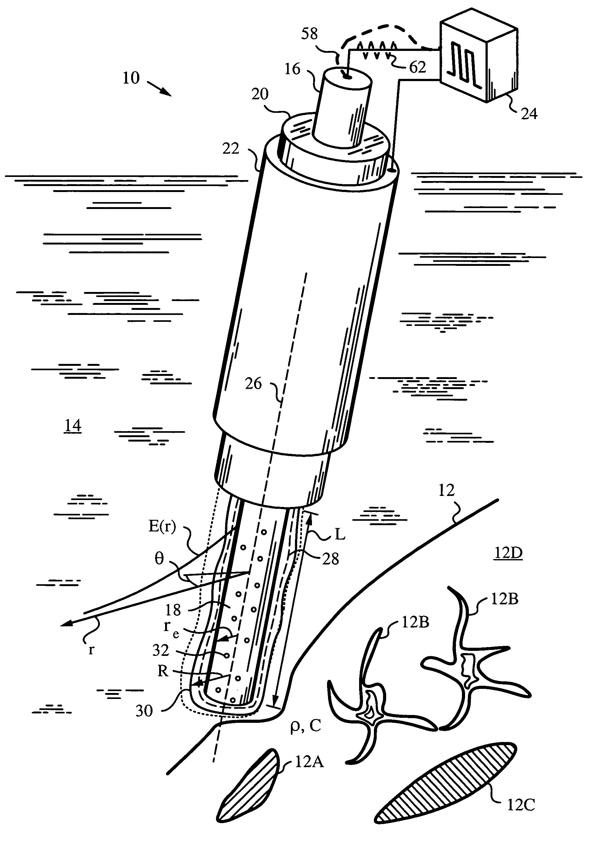
[0038]FIG. 1 illustrates an apparatus 10 for cutting a material 12 submerged in a conducting liquid medium 14. In this embodiment material 12 is a biological tissue made up of various types of tissue including muscle tissue 12A, nerve tissue 12B, bone 12C and soft tissue 12D. In general, however, material 12 can be any conducting or non-conducting material which requires cutting and can include materials such as cellulose, e.g., wood and cellulose-based materials as well as various types of non-conducting plastics. Liquid medium 14 can be any type of electrolyte. In the present embodiment, liquid medium 14 is a physiological medium, for example an isotonic saline solution.

[0039]Apparatus 10 has a cutting electrode 16 with an elongate cutting portion 18. In the present embodiment, entire cutting electrode 16 is in the form of a wire electrode with circular cross section defined by a radius re. The material of wire electrode 16 can be any suitable conductor such as a metal like Tungst...


PUM


Abstract

An apparatus and method for cutting a material including conducting and non-conducting materials such as biological tissue, cellulose or plastic while the material is submerged in a conductive liquid medium. The apparatus has a cutting electrode with an elongate cutting portion having an aspect ratio (length to width) of 1 or more and a return electrode. The two electrodes are immersed in the conductive medium and a voltage is applied between them to heat the medium, thus producing a vapor cavity around the elongate cutting portion and ionizing a gas inside the vapor cavity to produce a plasma. The voltage applied between the electrodes is modulated in pulses having a modulation format selected to minimize the size of the vapor cavity, its rate of formation and heat diffusion into the material while the latter is cut with an edge of the elongate cutting portion. The modulation format includes pulses ranging in duration from 10 μs to 10 ms, as well as minipulses and micropulses, as necessary. The apparatus and method of invention allow the user to perform efficient thermal ablation and electrosurgical procedures in particular at power levels as low as 10 mW with minimal thermal and cavitation damage.

Description

GOVERNMENT SPONSORSHIP[0001]This invention was supported by the National Institutes of Health under contract number RO1 EY 12888-02. The government has certain rights in this invention.FIELD OF THE INVENTION[0002]The present invention relates to an apparatus for cutting materials including biological tissue by thermo-electrical ablation with the aid of a plasma produced around a cutting electrode and to a method for driving such electrode with appropriate pulses.BACKGROUND[0003]The cutting of materials with the aid of cutting electrodes energized by a suitable power source is a known technique that is being successfully employed, e.g., in the field of electrosurgery. Typical electrosurgical devices apply a electrical potential difference or a voltage difference between a cutting electrode and a patient's grounded body (monopolar arrangement) or between a cutting electrode and a return electrode (bipolar arrangement) to deliver electrical energy to the area where tissue is to be cut....

Claims


Application Information

Patent Timeline
Patent Type & Authority Patents(United States)
IPC IPC(8): A61B18/18A61B18/14
CPCA61B18/042A61B18/14H05H1/24A61B2018/00577A61B2018/00601A61B2018/00625A61B2018/1213A61B2018/122A61B2018/1472H05H1/48H05H2245/32
Inventor PALANKER, DANIEL V.VANKOV, ALEXANDER B.
Owner THE BOARD OF TRUSTEES OF THE LELAND STANFORD JUNIOR UNIV
Why Eureka
Try Eureka