Camera and device for switching optical filters

a technology of optical filter and camera, applied in the direction of camera filter, exposure control, instruments, etc., can solve the problems of reducing sensitivity, affecting the operation of the camera, and unable to obtain clear images, etc., to prevent the camera from malfunctioning

Inactive Publication Date: 2007-07-03
PANASONIC CORP
View PDF29 Cites 25 Cited by
  • Summary
  • Abstract
  • Description
  • Claims
  • Application Information

AI Technical Summary

Benefits of technology

[0023]According to the method of the item (7), also in the case in which a bright object is locally present in the image pick-up environment so that the image pick-up environment cannot be decided from an image signal, th

Problems solved by technology

Moreover, if a sensitivity is set to obtain a clear image during the day, the sensitivity is reduced at night so that a clear imag

Method used


Image

  • Camera and device for switching optical filters
  • Camera and device for switching optical filters
  • Camera and device for switching optical filters

Examples


Embodiment Construction

[0031]An embodiment of the invention will be described in detail with reference to the drawings.

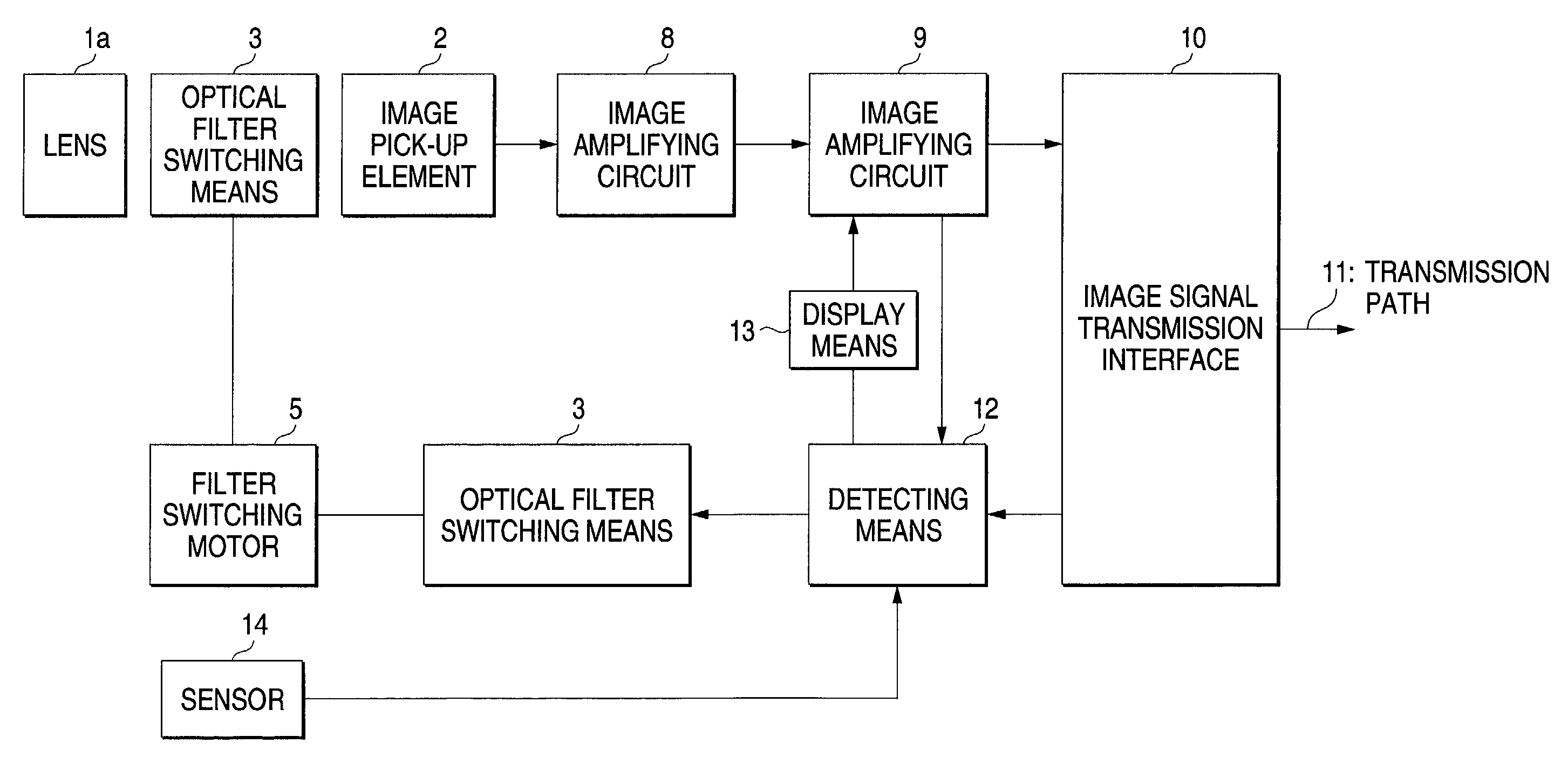
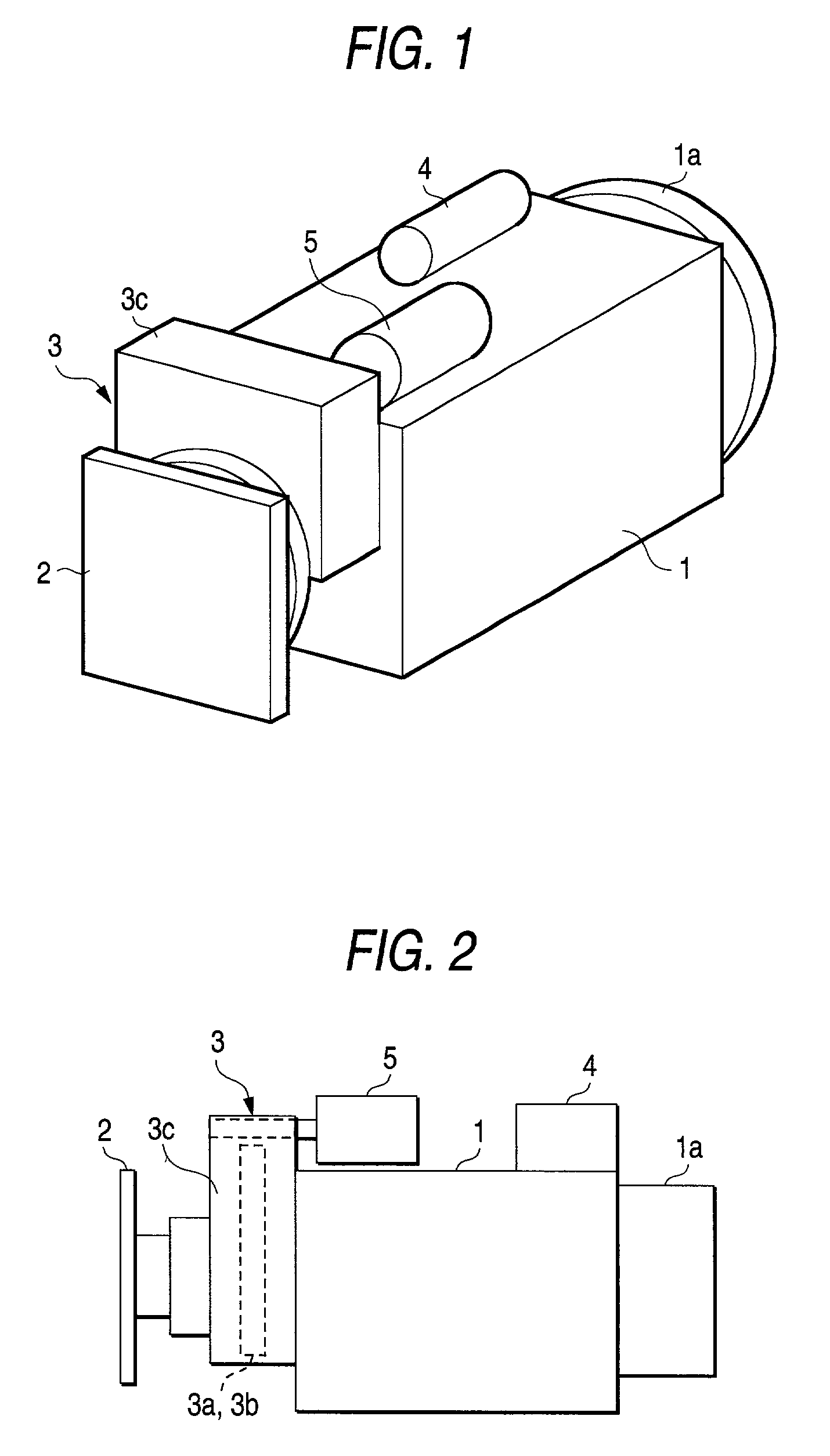
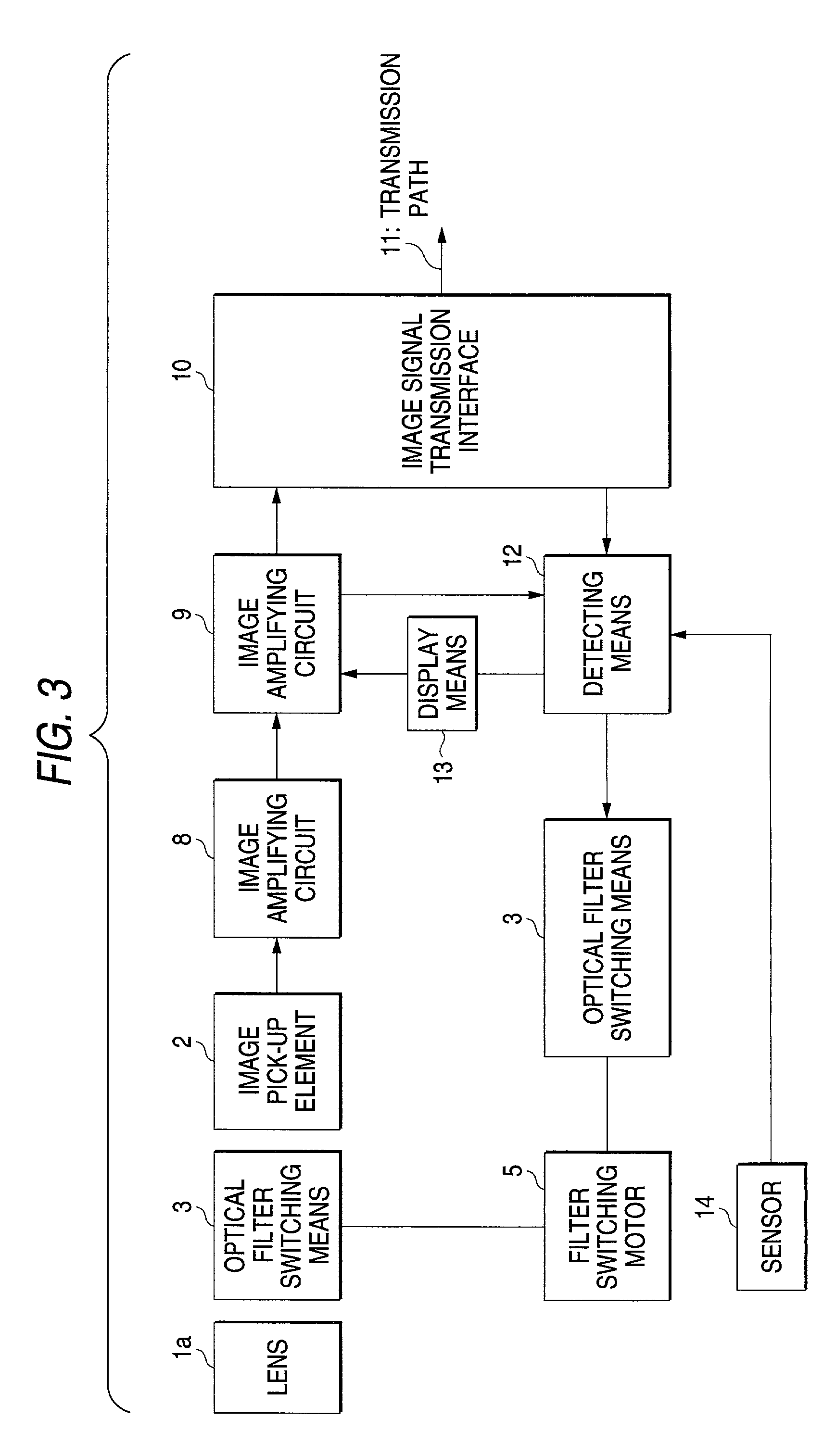
[0032]FIG. 1 is a perspective view showing a composite camera to be used for a surveillance camera, FIG. 2 is a side view showing the same composite camera, FIG. 3 is a block diagram showing a control system, FIG. 4 is a view illustrating the action of an optical filter switching device, FIG. 5 is a chart showing a frequency characteristic of an image pick-up element, and FIG. 6 is a flow chart showing a method of switching an optical filter of the composite camera.

[0033]In FIGS. 1 and 2, a camera body 1 has a lens 1a provided on a front surface and an image pick-up element 2 provided on the rear surface side in a focal position of the lens 1a. An image is formed on an image pick-up element 2 through the lens 1a and optical filter switching means 3 is provided between the rear surface of the camera body 1 and the image pick-up element 2.

[0034]To an upper surface of the camera body 1 are a...


PUM


Abstract

To provide an optical filter switching device for a camera in which a clear image can always be obtained during the day and at night.
In a cameral in which an image is formed on an image pick-up element (2) through a lens (1a) provided on a camera body (1) and is converted into an electric signal through the image pick-up element (2), thereby obtaining an image signal, optical filter switching means (3) for switching optical filters (3a) and (3b) depending on a level of the image signal is provided on a front surface of the image pick-up element (2) and a clear image can always be obtained during the day and at night. Therefore, in the case in which such a camera is used for a surveillance camera, the reliability of a monitoring system can be enhanced.

Description

TECHNICAL FIELD[0001]The present invention mainly relates to a camera to be used for a surveillance camera and an optical filter switching method thereof.BACKGROUND ART[0002]Conventionally, a composite camera such as a dome camera has been used for a surveillance camera constituting a monitoring system.[0003]The composite camera uses a semiconductor image pick-up element (which will be hereinafter referred to as an image pick-up element) such as a CCD or a C-MOS.[0004]In the image pick-up element, a sensitivity of an infrared region is much higher than a visible light level. In order to obtain a color image, therefore, an infrared cut filter is provided on the front surface of the image pick-up element to cut unnecessary infrared rays.[0005]On the other hand, the surveillance camera needs to continue monitoring for twenty-four hours. Therefore, it is necessary to use a composite camera having a great dynamic range capable of clearly obtaining a bright image during the day and a dark...

Claims


Application Information

Patent Timeline
IPC IPC(8): H04N5/225G02B5/20G03B7/18G03B11/00G03B11/06G03B15/00G03B17/20H04N5/238H04N5/33H04N7/18
CPCG03B7/18G03B11/06G08B13/19626G08B13/19695H04N5/2254H04N7/183H04N5/33H04N23/55
Inventor IKOMA, KENTAMURA, KAZUSHIGETAKAKUWA, MAKOTO
Owner PANASONIC CORP
Why Eureka
Try Eureka