Formation imaging while drilling in non-conductive fluids

a technology of non-conductive fluids and formation imaging, which is applied in the direction of reradiation, instruments, and borehole/well accessories, etc., can solve the problems of dc giving rise to noise problems, difficult to work with, and difficult to obtain good quality images

Inactive Publication Date: 2007-07-10
SCHLUMBERGER TECH CORP
View PDF28 Cites 76 Cited by
  • Summary
  • Abstract
  • Description
  • Claims
  • Application Information

AI Technical Summary

Problems solved by technology

However the taking of such cores is a technique that is extremely expensive, and use thereof remains relatively exceptional.
However, with muds having a continuous non-conductive phase, such as oil-base muds or water-in-oil emulsion type muds, the images obtained are of very poor quality.
These poor results are generally attributed to interference due to the presence of a layer of non-conductive mud, or of a layer of mud and a mud cake, interposed between the buttons and the formation under test.
However, in practice, working with DC gives rise to problems of noise due in particular to the formation of spontaneous potentials in the formation.
In addition, the resistance of the mud limits the quantity of current injected; the potential differences measured between two pairs of buttons are thus very small and therefore difficult to measure.
Unfortunately, at such frequencies, the pad behaves like a dielectric whose effective conductivity is similar to that of the mud.
Under such conditions, the potential differences between pairs of buttons are more representative of the potential difference applied between the current electrodes than they are of the resistivity of the formation facing them, therefore, the tool becomes unusable.
The major limitation of the measurement is that the pad must be close to the borehole wall, especially in low-resistivity formations.
As a result, when the borehole is rough the images are spoiled by incorrect readings and become uninterpretable.
While the above-described tools are capable of providing images of boreholes drilled with non-conductive muds, they are wireline tools and are not suitable for logging-while-drilling applications.

Method used


Image

  • Formation imaging while drilling in non-conductive fluids
  • Formation imaging while drilling in non-conductive fluids
  • Formation imaging while drilling in non-conductive fluids

Examples


first embodiment

[0063]A first embodiment consists of a conductive metallic pad structure that contains insulating inserts around the source and return electrodes and measurement electrodes. Therefore, in this embodiment of an apparatus according to the invention, it is the conductive pad itself that shields the measurement electrodes.

[0064]The conductive pad 90 is held at a potential close to that of the formation in front of the measurement electrodes. For example, in one preferred implementation the pad is driven at the measured potential of the formation in front of the measurement electrodes 6. As mentioned in the PCT Patent Application PCT / EP01 / 03718 A1, an electronic circuit, not shown, averages all the potential values measured by all the measurement electrodes.

second embodiment

[0065]A second embodiment consists of a pad made of insulating material and shielding means constituted of conducting (e.g., metallic) sheets. In order not to weaken the outside parts of the shielding sheets can be molded inside the pad. Alternatively, conductive sheets can be placed on both the inside face and the outside face of the pad.

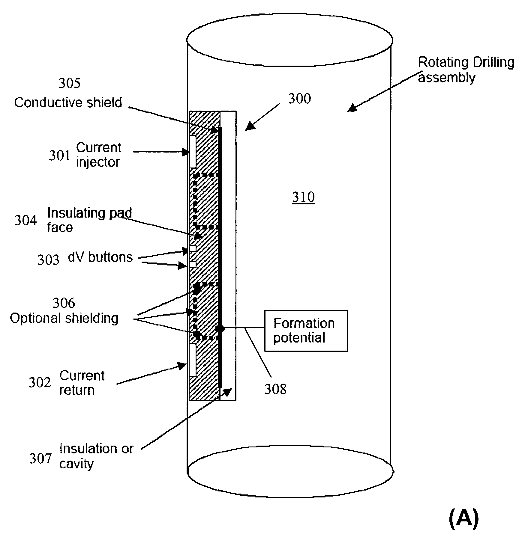
[0066]FIG. 6 shows one embodiment of a sensor having an insulating face and a conductive backplate disposed on an LWD tool. As shown, a sensor 300 in accordance with one embodiment of the invention is disposed on a rotating drilling assembly 310. The sensor 300 comprises a current injection electrode 301, a current return electrode 302, and an array of measurement electrodes 303, all of which disposed on an insulating pad 304. In addition, a conductive shield (or conductive backplate) 305 is disposed behind the electrodes, but insulated from the conductive drilling assembly 310 by an insulation layer or cavity 307. The sensor 300 may optionally inc...


PUM

PropertyMeasurementUnit
frequencyaaaaaaaaaa
frequenciesaaaaaaaaaa
current pathaaaaaaaaaa

Abstract

A resistivity tool for investigating a wall of a borehole drilled with a non-conductive mud includes a tool body adapted to be incorporated in a logging-while-drilling tool assembly; a resistivity sensor disposed on the tool body, wherein the resistivity sensor comprises a sensor pad supporting a current injector electrode, a current return electrode, and an array of measurement electrodes, and a circuitry for controlling current injection from the current injector electrode and for measuring voltage difference between electrodes in the array of measurement electrodes, wherein the current injector electrode and the current return electrode are disposed near opposite ends of the sensor pad and the array of measurement electrodes is disposed between the current injector electrode and the current return electrode, wherein the sensor pad is constructed of an insulating material and includes a conductive shielding member, or wherein the sensor pad is constructed of a conducting material and includes insulating sections around the electrodes.

Description

CROSS-REFERENCE TO RELATED APPLICATIONS[0001]This is a Continuation-In-Part of U.S. patent application Ser. No. 10 / 240,639, “Logging Sonde For Electrically Exploring Geological Formations Through Which A Borehole Passes,” filed on Mar. 4, 2003 now U.S. Pat. No. 6,891,377 by Cheung et al., which claims priority from PCT Application PCT / EP01 / 03718 filed on Mar. 29, 2001 and claims priority from French Application No. FR20000004527 filed on Apr. 7, 2000.BACKGROUND OF INVENTION[0002]1. Field of the Invention[0003]The invention relates generally to well logging using a resistivity tool; more particularly, it relates to resistivity logging while drilling in a well drilled with a nonconductive mud.[0004]2. Background Art[0005]In general terms, in order to explore hydrocarbon deposits, it is highly desirable to obtain accurate knowledge of the characteristics of the geological formation at various depths of the borehole. Many of these characteristics are very fine in structure, e.g. stratif...

Claims


Application Information

Patent Timeline
Patent Type & Authority Patents(United States)
IPC IPC(8): G01V3/18E21B49/00G01N3/20G01V3/20G01V3/24
CPCG01V3/24
Inventor HAYMAN, ANDREW J.CHEUNG, PHILIP
Owner SCHLUMBERGER TECH CORP
Why Eureka
Try Eureka