Liquid cooling system and an electronic apparatus applying the same therein

a liquid cooling and electronic equipment technology, applied in the direction of power cables, cables, instruments, etc., can solve the problems of limited cooling methods relating to those conventional arts, and difficult to maintain the reliability of using liquid for cooling

Inactive Publication Date: 2007-07-10
HITACHI LTD
View PDF13 Cites 14 Cited by
  • Summary
  • Abstract
  • Description
  • Claims
  • Application Information

AI Technical Summary

Benefits of technology

[0016]Then, an object is, according to the present invention, by taking the problems within such the conventional arts as was mentioned above into the consideration, and in more details thereof, to provide a liquid cooling system, being applicable to the electronic apparatus, easily, which includes a material dissolving the corrosive ion in a part thereof, such as, the personal computer or the like, for example, while enabling to maintain the corrosion resistance thereof for a long time-period (for example, the term of guarantee: 5–10 years), with certainty, thereby being able to operate, safely, but irrespective of use of the liquid coolant or refrigerant therein, and further, to provide an electronic apparatus applying the same therein.

Problems solved by technology

However, the cooling methods relating to those conventional arts are limited, in particular, only to a use in a large-scaled computer (or, so-called a mainframe).
A reason thereof lies in that the liquid cooling apparatus comes to be large in the sizes, because such the liquid cooling system relating to the conventional arts mentioned above needs a large number of parts, which are exclusive use for the liquid cooling, such as, a pump, a piping system, a radiator, etc., and further, in that it is difficult to maintain the reliability of using a liquid for cooling, comparing to other cooling method.
However, as was mentioned above, the heat-generation goes up, every year, of the semiconductor element, being the heat-generation parts to be used within those electronic apparatuses, as such, the personal computer, the home server, the projector, and the media storage, etc., in particular, in recent years, and therefore, the cooling comes to be insufficient, obtained by means of such the air-cooling using the heat-conduction and / or a forced circulation air-cooling of the conventional arts, or the cooling through the heat pipe, only.
However, installing such the liquid cooling system of using the liquid coolant or refrigerant into an inside of the personal computer further causes a new problem.
For this reason, if corrosive ion dissolves from a portion in contact with the coolant or refrigerant, even in a small amount thereof, in particular, from the parts made of organic materials (i.e., parts made of synthetic resin), then due to that corrosive ion, the liquid quality of the cooling liquid, being small in the amount thereof, is easily degraded as a whole; i.e., there is a problem that corrosion is promoted, in particular, upon the parts made of the metal materials, such as, the heat-receiving jacket and / or the radiator, etc.
And further, such the problem is fatal, in particular, for the liquid cooling system to be applied within the electronic apparatus, including the personal computer therein, since it is desirable that those parts, including piping portions therein, are made of the metal materials as far as they can, for the purpose of lowering leakage of the liquid coolant or refrigerant held within the inside, through vaporization thereof, and thereby maintaining the cooling operation for a long time-period (for example, around 5–10 years as a term of guarantee).
Moreover, in a case if causing the water leakage due to such the corrosion, it also causes an important problem, such as, that the functions of the electronic apparatus are stopped, or the like; therefore, it is indispensable to apply a countermeasure for the corrosion control (or, an anticorrosive means) upon the parts, which are in contact with the cooling liquid.

Method used


Image

  • Liquid cooling system and an electronic apparatus applying the same therein
  • Liquid cooling system and an electronic apparatus applying the same therein
  • Liquid cooling system and an electronic apparatus applying the same therein

Examples


Embodiment Construction

[0046]Hereinafter, embodiments according to the present invention will be fully explained by referring to the attached drawings.

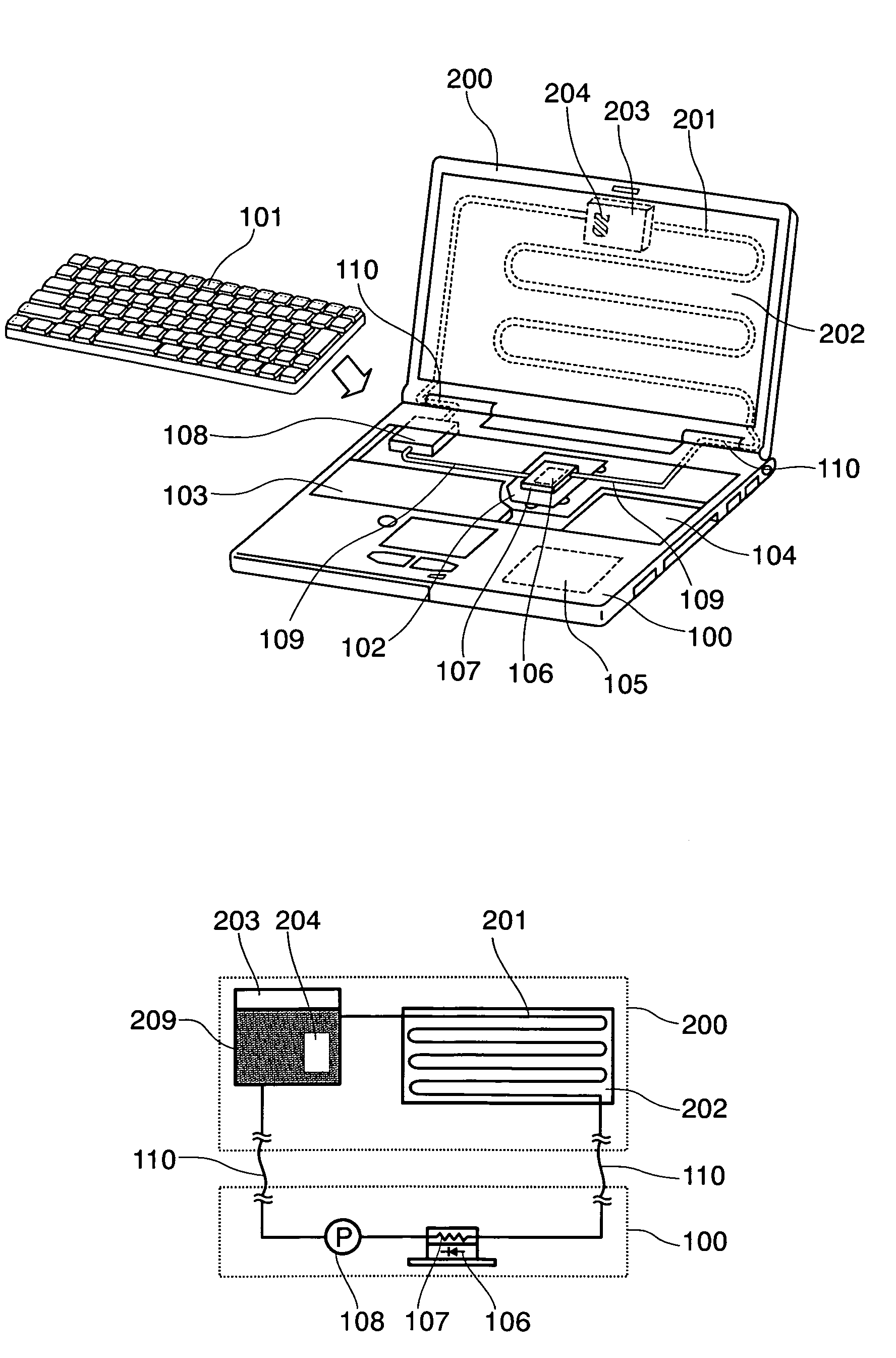
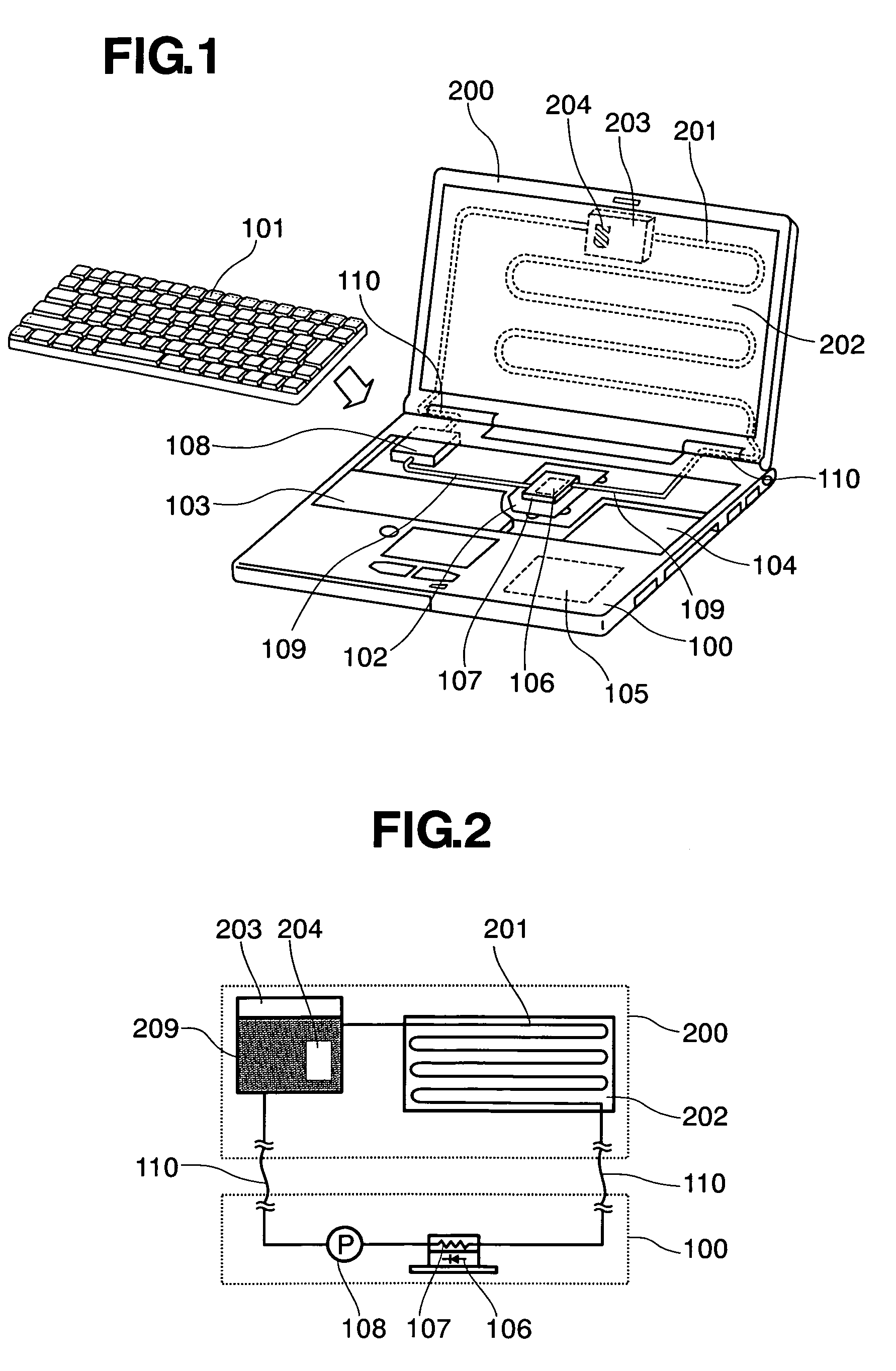
[0047]First of all, FIG. 1 attached herewith is a perspective view of a notebook-type personal computer, as being an electronic apparatus applying a liquid cooling system therein, according to one embodiment of the present invention. Herein, though explanation will be made only about the notebook-type personal computer, as being the most familiar one thereof, as one embodiment thereof; however, it is needless to say that the present invention should not be restricted only to such the notebook-type personal computer, but it is also applicable to various kinds of the electronic apparatuses, such as, the desktop-type personal computer, the home server, the projector, and the media storage, etc., for example, as was mentioned above.

[0048]The electronic apparatus comprises a main housing 100, and a display housing 200 having a liquid crystal display device there...


PUM


Abstract

A liquid cooling system, enabling protection from corrosion due to liquid coolant for a long time-period (5–10 years) while cooling a heat-generation body effectively, comprises a pump 108, a heat-receiving jacket 107, a radiator for radiating heat into an outside, being made up with a heat-radiation pipe 201 and a heat-radiation plate 202, and further a tank 203 for accumulating the liquid coolant 209 within an inside thereof, wherein those are connected in a closed-loop, so as to circulating the cooling liquid therein, thereby cooling the heat-generation of a CPU 106, being a heat-generation element, effectively, through the heat-receiving jacket 107, and further a water-permeable bag 204 is disposed in a portion of flow path of the cooling liquid, which receives microcapsules 10 therein, each enclosing in an inside thereof anti-corrosion agent 20 for suppressing the corrosion due to the cooling liquid, including such as, a water, etc.

Description

BACKGROUND OF THE INVENTION[0001]The present invention relates to a liquid cooling system, being suitable for use within an electronic apparatus, including such as a notebook-type personal computer, for example, and further a desktop-type personal computer, a home server, a projector, and a media storage, etc., wherein cooling can be achieved, effectively, through the liquid cooling, and further relates to an electronic apparatus using the liquid cooling system therein.[0002]A semiconductor element, which is applied within the electronic apparatus, such as, the computer or the likes mentioned above, in particular, a CPU, generating heat when it operates, as being a representative one of such the semiconductor elements. In particular, in recent years, due to demands for high speed of processing and / or high capacity, upon such the semiconductor elements, a value of heat-generation therefrom is in a tendency of increasing, more and more. Since such the semiconductor element loses the f...

Claims


Application Information

Patent Timeline
Patent Type & Authority Patents(United States)
IPC IPC(8): H05K7/20G06F1/20
CPCC09K5/10G06F1/203F28D15/00F28F19/00G06F2200/201G06F2200/203H05K7/20
Inventor MINAMITANI, RINTAROMATSUSHITA, SHINJI
Owner HITACHI LTD
Why Eureka
Try Eureka