Apparatus, system, and method of joining structural components with a tapered tension bond joint

a technology of tapered tension and tapering joints, applied in the field of joints for structural components, can solve the problems of increasing fabrication time, requiring expensive and time-consuming drilling and fastening operations, and weakening the structure, so as to improve ballistics survivability, stop crack formation, and reduce the cost

Inactive Publication Date: 2007-07-17
LOCKHEED MARTIN CORP
View PDF18 Cites 66 Cited by
  • Summary
  • Abstract
  • Description
  • Claims
  • Application Information

AI Technical Summary

Benefits of technology

[0011]In the preferred embodiment, the flat panel spars are designed with a series of imbedded nut elements in the receptacle that serve as “internal tooling” to provide a positive stop for locating the lower skin, as well as a means for clamping the lower skin to the upper assembly during the closeout operation. The blade has mating recesses to receive the nut elements. The disruption of the closeout joint by the imbedded nuts gives the final assembled structure a very significantly enhanced ballistics survivability. The nuts act to stop cracks formed in the structure when the structure is impacted. A very significant amount of tolerance is allowed for the fit between the blade and the slot, thereby reducing the cost associated with highly accurate 3-D joints.

Problems solved by technology

Closeout panels can present problems for manufacturers, in that panels may attach to a substructure without access to the backside of the panel.
These methods require expensive and time-consuming drilling and fastening operations and may weaken the structure.
Because of the inferior bonding characteristics of laminating resins, a thin layer of adhesive is often placed between the preform and the components.
Generally, an adhesive film is used, which is expensive and adds to fabrication time.
Methods for ensuring proper bonding may include tools, such as molds or vacuum bags, but particular applications may prevent the use of tools due to the inaccessibility of one or both sides of the joint.

Method used


Image

  • Apparatus, system, and method of joining structural components with a tapered tension bond joint
  • Apparatus, system, and method of joining structural components with a tapered tension bond joint
  • Apparatus, system, and method of joining structural components with a tapered tension bond joint

Examples


Embodiment Construction

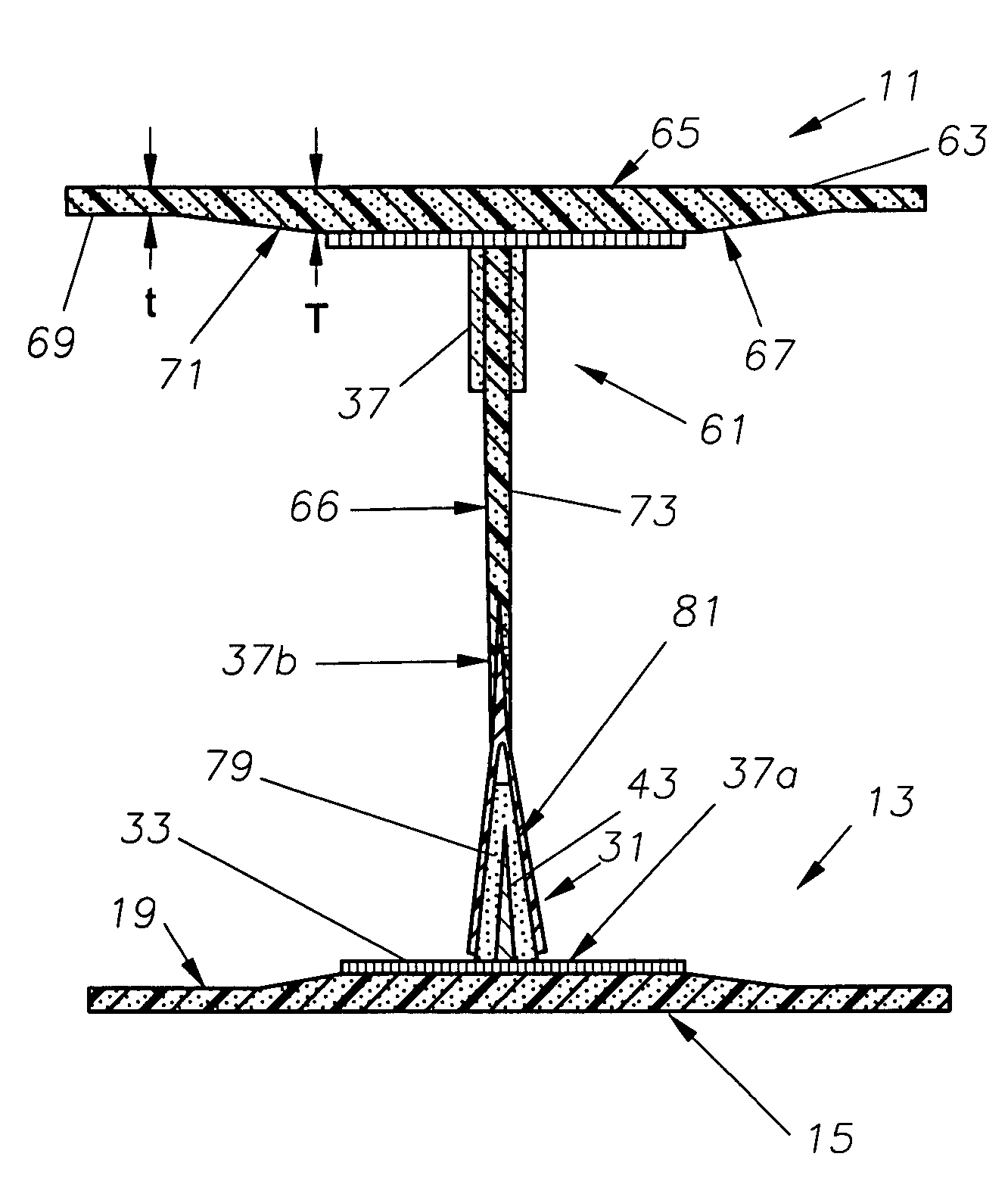
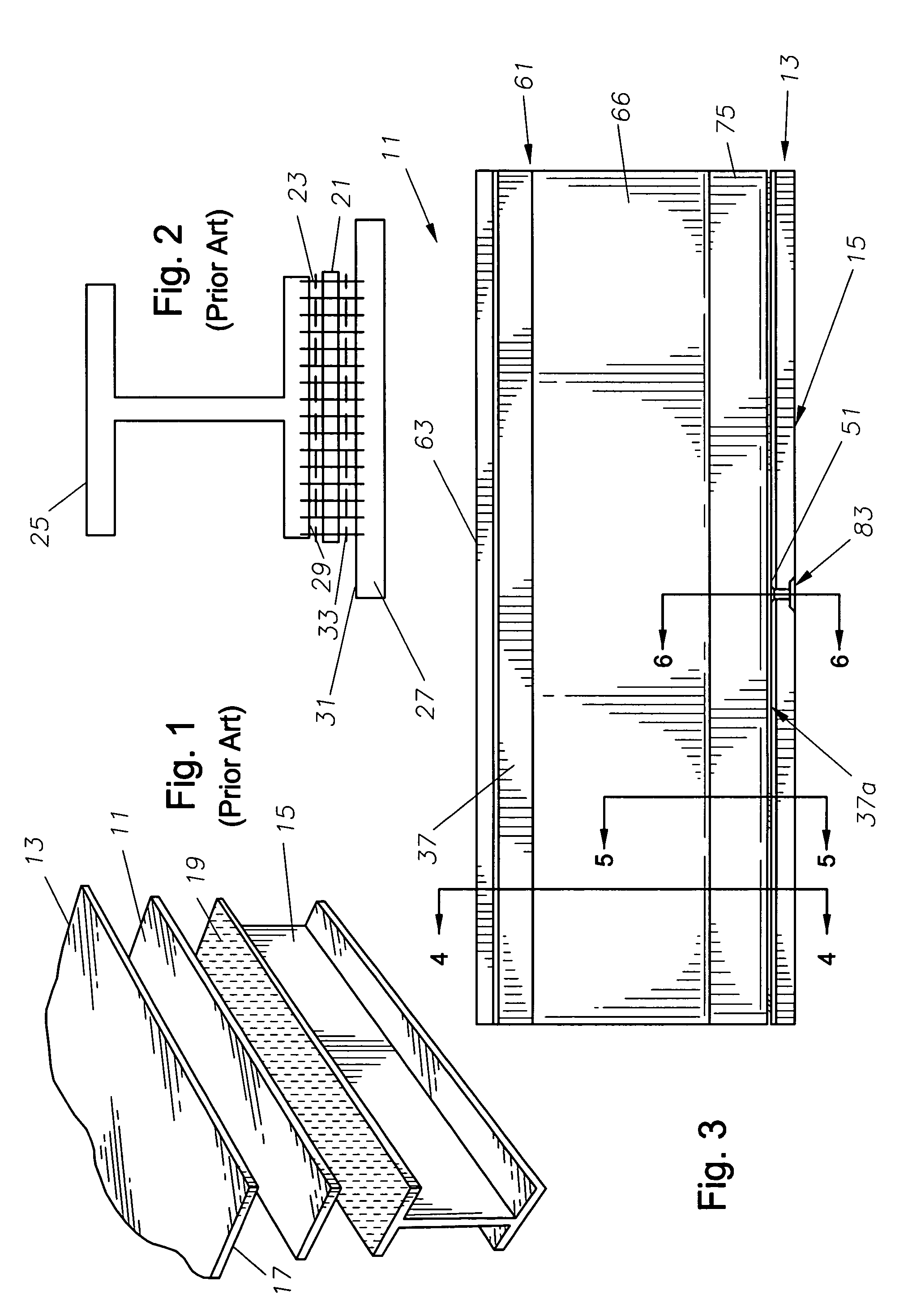
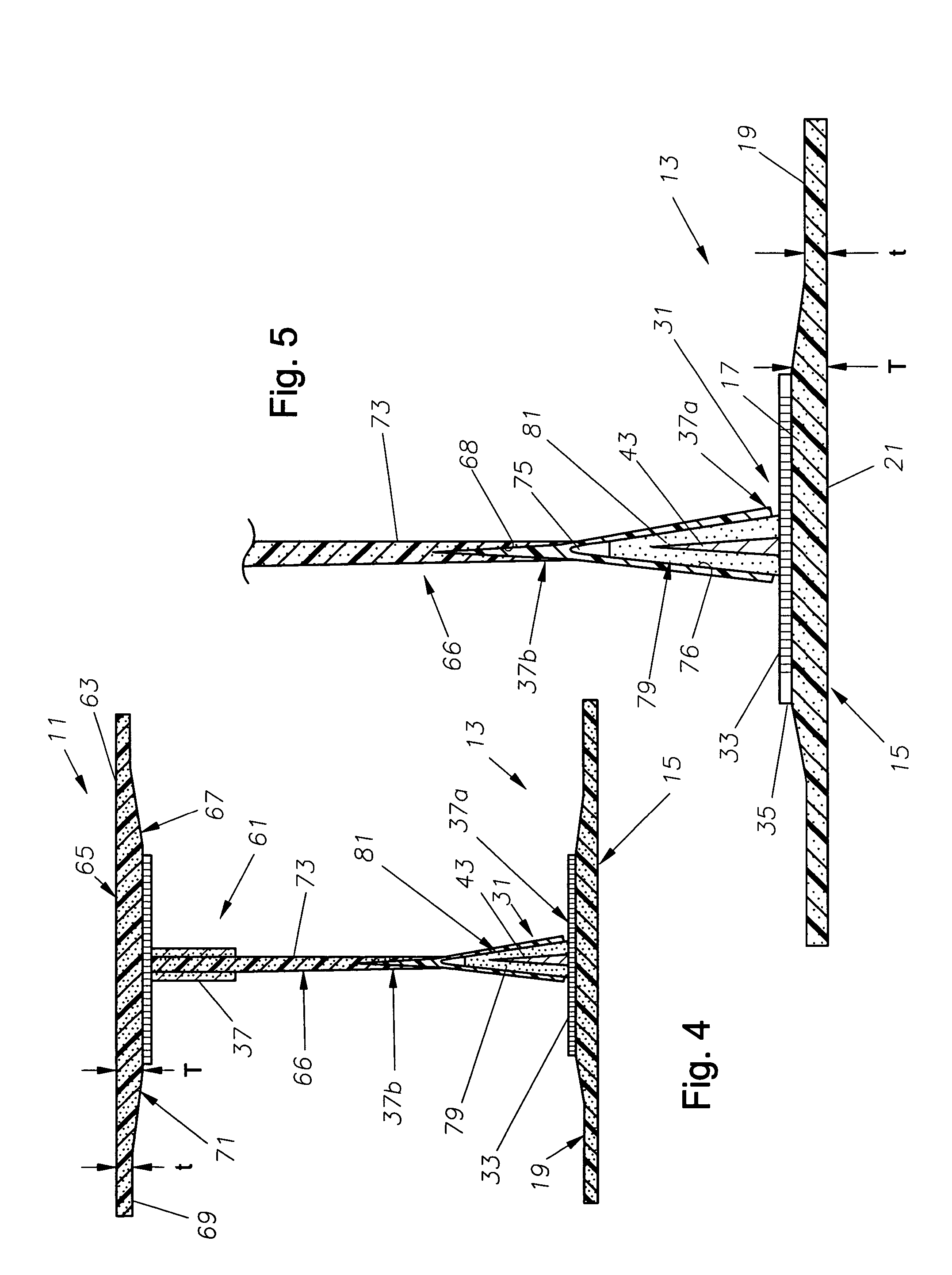
[0025]Referring to FIGS. 3 and 4, one embodiment of a structural assembly 11 constructed in accordance with the present invention is shown. In the embodiment shown, the structural assembly 11 includes a joint component, e.g., a closeout assembly 13 (FIG. 5). Closeout assembly 13 has a composite first structural member comprising an external surface 15 and a plurality of internal joint surfaces 17 located opposite the external surface 15. In one version, the external surface 15 is formed by a “closeout skin” comprising a co-bonded laminated composite. The closeout assembly 13 has nominal regions 19 and each of the internal joint surfaces 17 is located on a built-up region 21. The nominal regions 19 have a thickness “t” that is less than a thickness “T” of the built-up regions 21.

[0026]The closeout assembly 13 also includes a plurality of protrusions 31 (one shown in FIG. 5). Each of the protrusions 31 extends from a respective one of the internal joint surfaces 17. The protrusions 31...


PUM

PropertyMeasurementUnit
thicknessaaaaaaaaaa
shapeaaaaaaaaaa
distanceaaaaaaaaaa

Abstract

A system of composite and adhesive materials provides for a high strength, producible closeout joint in the form of tapered tension bond joint for high performance structures. The system includes one skin that is co-bonded to flat panel spars, with the joint being positioned at the opposite side of the spars. The spar includes a female receptacle that receives a male blade from the closeout skin assembly. The blade and receptacle are wedge-shaped woven preforms. The flat panel spars have imbedded nut elements that serve as “internal tooling” to provide a positive stop for locating and clamping the structural members together.

Description

CROSS-REFERENCE TO RELATED APPLICATION[0001]This application is a continuation-in-part of application Ser. No. 10 / 422,254, filed Apr. 24, 2003, now abandoned.BACKGROUND OF THE INVENTIONTECHNICAL FIELD[0002]The present invention relates in general to an improved joint for structural components, and in particular to an improved apparatus, system, and method for forming a tapered tension bond joint between structural components.BACKGROUND OF THE INVENTION[0003]Closeout panels can present problems for manufacturers, in that panels may attach to a substructure without access to the backside of the panel. In the past, these panels have been bolted to the substructure or attached using blind fasteners, such as pull rivets. These methods require expensive and time-consuming drilling and fastening operations and may weaken the structure. More recently, these panels have been co-bonded or secondarily bonded using resin or a thin layer of adhesive.[0004]Typically, laminating resins are used as...

Claims


Application Information

Patent Timeline
Patent Type & Authority Patents(United States)
IPC IPC(8): B32B3/26B29C65/00B29C65/48B29C65/56B29C65/72B32B3/02B32B7/08F16B5/02F16B11/00
CPCB29C65/562B29C65/564B29C65/72B29C66/43441B29C66/721B32B3/02B32B7/08F16B11/006B29C65/561B29C66/52441B29C66/12441B29C66/12464B29C65/48B29C65/56Y10T428/24174F16B5/02Y10T403/47B29C65/483B29C66/543B29C66/7212B29C66/72141B29K2277/10
Inventor BRANTLEY, JERRY W.RODENBERGER, CHARLES MARK
Owner LOCKHEED MARTIN CORP
Why Eureka
Try Eureka