Allocation of upstream bandwidth in an ethernet passive optical network

a passive optical network and upstream bandwidth technology, applied in data switching networks, multiplex communication, digital transmission, etc., can solve the problems of inability to handle burst traffic, increased polling cycle disadvantages of simple hub polling, and even more pronounced problems, so as to reduce delay and/or jitter, and eliminate the effect of related delay variation and/or jitter variation

Inactive Publication Date: 2007-07-17
SALIRA SYST
View PDF10 Cites 48 Cited by
  • Summary
  • Abstract
  • Description
  • Claims
  • Application Information

AI Technical Summary

Benefits of technology

[0019]A passive optical network (PON) uses a superframe having a number of frames that are sequentially transmitted (i.e. one after another) with each frame having a number of subframes that are also sequentially transmitted, wherein an optical line terminal (OLT) in accordance with the invention allocates to each optical network unit (ONU), for upstream transmission of information, a number of subframes that are deliberately spaced apart from one another so that subframes are allocated throughout a superframe as evenly as possible. Distancing of subframes allocated to the same optical network u

Problems solved by technology

If a packet cannot be completely transmitted within a current time slot, it is transmitted in the next slot Although there are no collisions and no packet fragmentation, such a fixed round-robin slot allocation cannot handle bursty traffic situations.
However, as noted in the just-described article, simple hub polling has a disadvantage of increasing the polling cycle due to accumulation of walk times (switchover times).
In access networks, this problem is even more pronounced than in LANs, as the propagation delays in the access network are much

Method used


Image

  • Allocation of upstream bandwidth in an ethernet passive optical network
  • Allocation of upstream bandwidth in an ethernet passive optical network
  • Allocation of upstream bandwidth in an ethernet passive optical network

Examples


Embodiment Construction

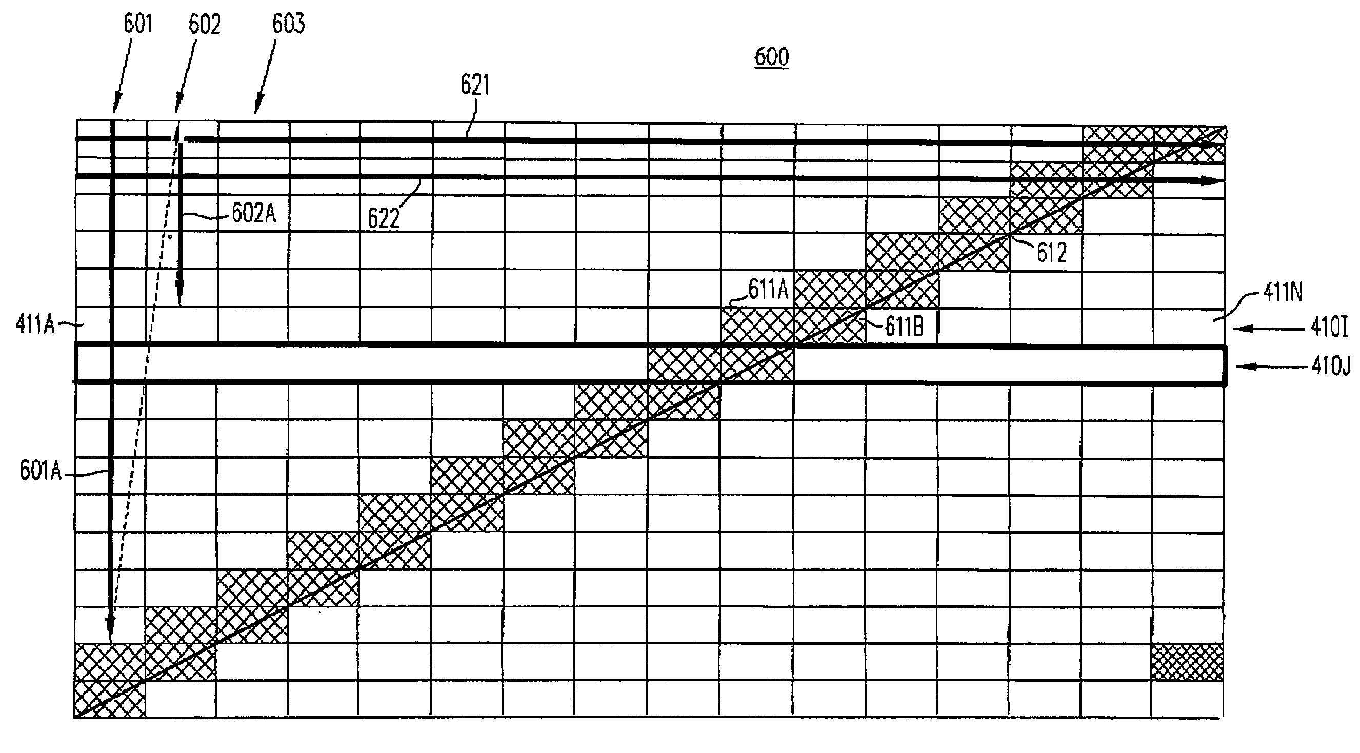
[0048]A number of optical network units (ONUs) communicate with an optical line terminal (OLT) in a passive optical network (PON) in accordance with the invention by transmitting upstream signals in a superframe 400 (FIG. 4A). A similar superframe may be used by the OLT in communicating in the downstream direction with the ONUs. Each of the ONUs and the OLT are equipped with hardware of the type well known in the art for implementing a PON. The PON is implemented with an optical branching / coupling element between the ONUs and the OLT. The optical branching / coupling element is a passive device that does not need an electric source. The OLT is connected to the optical branching / coupling element through a single optical fiber (or a double optical fiber for redundancy). Each of the ONUs is connected to the optical branching / coupling element through an exclusive optical fiber.

[0049]Each of the ONUs and OLT may contain a central processing unit (CPU) that controls operation of a media acc...


PUM


Abstract

A passive optical network (PON) in accordance with the invention uses a superframe having a number of subframes arranged in a two-dimensional array, wherein for normal data transfer subframes are allocated to each optical network unit (ONU) column by column, left to right, and within each column subframes are allocated from top to the bottom. Initially, for ranging, at least two subframes are allocated to an ONU, adjacent to a diagonal of the superframe (which may go from the top left corner of the superframe to the bottom right corner, or alternatively from the top right corner to the bottom left corner). In some embodiments, instead of allocating subframes column by column, the subframes are evenly spaced apart from one another, and conflicts with a previous allocation are resolved by adjustment, and optionally an evaluation function may be used to find an optimal allocation.

Description

CROSS-REFERENCE TO RELATED APPLICATIONS[0001]This application is a continuation of and claims priority to the following U.S. Patent Applications that were filed as provisional applications.[0002]U.S. patent application Ser. No. 60 / 304,346 entitled “Bandwidth allocation algorithm in an EPON system”, filed on Jul. 10, 2001 by Haixing Shi, confirmation no. 6135; and[0003]U.S. patent application Ser. No. 60 / 304,322 entitled “Apparatus for bandwidth allocation in EPON to minimize delay and jitter variation”, filed on Jul. 10, 2001, by Ying He, Jack Zhang, Charlie Hou and Hok Lau, confirmation no. 9998.[0004]This application is also related to and incorporates by reference herein in its entirety a concurrently filed, commonly owned U.S. Patent Application entitled “Ethernet Passive Optical Network with Framing Structure for Native Ethernet Traffic and Time Division Multiplexed Traffic Having Original Timing” filed by Jian Song et al, Attorney Docket No. SAL003 US.[0005]Each of these three...

Claims


Application Information

Patent Timeline
IPC IPC(8): H04J3/16H04L12/56H04Q11/00
CPCH04J3/1694H04Q11/0062H04Q11/0067H04Q11/0066H04Q2011/0064
Inventor SHI, HAIXINGHE, YING
Owner SALIRA SYST
Why Eureka
Try Eureka