Low power, pulsed, electro-thermal ice protection system

a protection system and low-power technology, applied in the direction of machines/engines, mechanical equipment, transportation and packaging, etc., can solve the problems of 20° c, bare metal surface heater arrangement is not structurally sound, and the electro-chemical heating method fails to perform at low temperatures

Active Publication Date: 2007-07-24
THE BF GOODRICH CO
View PDF26 Cites 39 Cited by
  • Summary
  • Abstract
  • Description
  • Claims
  • Application Information

AI Technical Summary

Benefits of technology

[0009]In accordance with one aspect of the present invention, an electro-thermal ice protection system for an airfoil comprises: a metal foil heater including an integral parting strip, the metal foil heater configurable to cover at least a portion of a leading edge of the airfoil with the integral parting strip disposed along an air-stagnation zone of the leading edge; and a controller coupled electrically to the metal foil heater for controlling electrical energy from a power source to the metal foil of the heater in accordance with a pulse duty-cycle and for controlling power to the parting strip of the heater to maintain the air-stagnation zone virtually free of ice formation.
[0011]In accordance with yet another aspect of the present invention, an ice protection system for an airfoil comprises: at least one metal foil heater covering at least a portion of a leading edge of the airfoil, the at least one metal foil heater coupled at a region through a conductor to a conductive structure of the airfoil for distributing electrical energy of a lightning strike from the region through the conductor to the conductive structure; and a converter powered by a power source for supplying electrical heating energy to the at least one metal foil heater over source and return lines which are electrically isolated from the power source, the converter for preventing the electrical heating energy from being conducted through the conductive structure of the airfoil.
[0013]In accordance with yet another aspect of the present invention, an electro-thermal ice protection system for an airfoil comprises: a metal foil heater including a plurality of integral parting strip segments, the metal foil heater configurable to cover at least a portion of a leading edge of the airfoil with each integral parting strip segment of the plurality disposed along a corresponding segment of an air-stagnation zone of the leading edge; and a controller coupled electrically to the metal foil heater for controlling electrical energy from a power source to the metal foil of the heater and for controlling power to the plurality of parting strip segments of the heater to maintain at least a segment of the air-stagnation zone virtually free of ice formation.

Problems solved by technology

In addition, it was found that the electro-chemical heating method fails to perform at low temperatures, like below −20° C., for example, because the ice which is a protonic semiconductor is not conductive enough at these temperatures to allow significant power to be imparted at voltage levels that are consistent with safe aero design practice as dictated by the U.S. FAA regulations and FAA advisory circular bulletins such as AC 25.981, for example.
However, this bare metal surface heater arrangement was found not to be structurally sound when tested under airfoil flight conditions, especially under rain erosion and particulate abrasion conditions.
Any layer of material disposed over the heater grid for protection against rain erosion and particulate abrasion conditions will cause heat losses which will impose additional heating power requirements for ice protection.
Generally, power supply systems on-board the aero structure can not afford to provide such ice protection power without affecting the power requirements to other systems.

Method used


Image

  • Low power, pulsed, electro-thermal ice protection system
  • Low power, pulsed, electro-thermal ice protection system
  • Low power, pulsed, electro-thermal ice protection system

Examples


Embodiment Construction

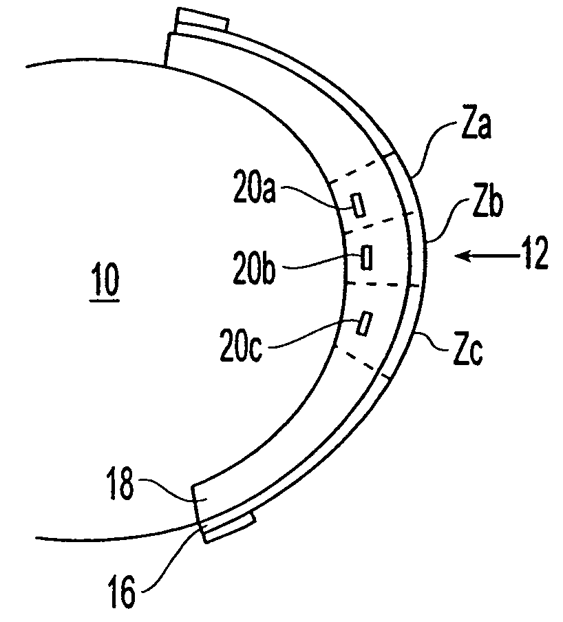
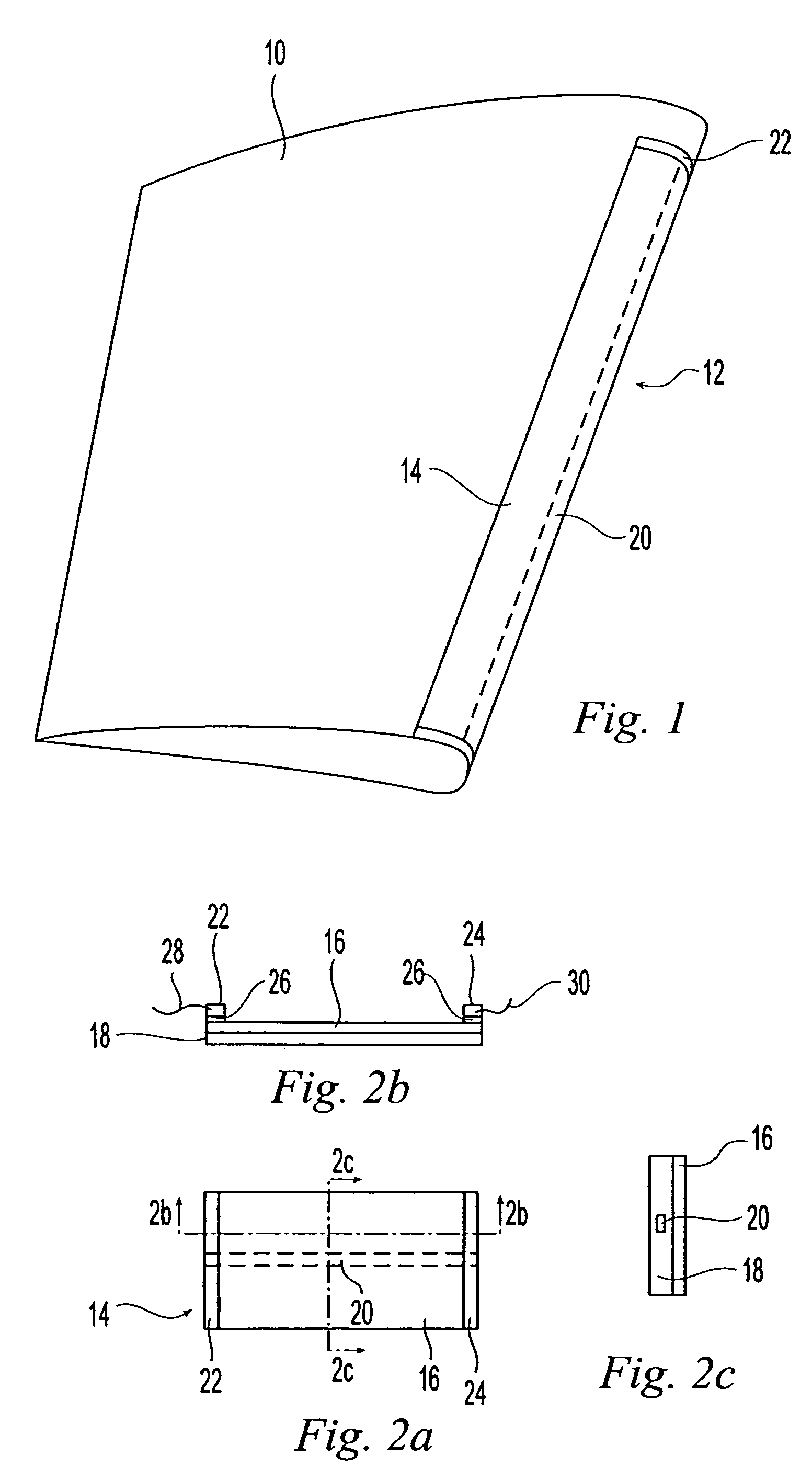
[0030]FIG. 1 is an isometric illustration of an airfoil section 10 of an aero structure suitable for embodying one aspect of the present invention. Referring to FIG. 1, wrapped around a leading edge 12 of the airfoil 10 in a C-shaped configuration is a metal foil heater 14. The metal material of foil heater 14 should be durable under and resistant to flight conditions of the airfoil 10, such as raindrop erosion and particulate abrasion, for example. In the present embodiment, the foil heater 14 comprises a rectangular sheet of Titanium having a thickness of approximately 0.004 inches or 4 mils with dimensions of approximately 66 inches in length and approximately 11 to 13 inches in width, for example.

[0031]An exemplary Titanium foil heater 14 suitable for embodying the principles of the present invention is shown in plan, side and profile views in FIGS. 2A, 2B and 2C, respectively. Referring to FIGS. 2A, 2B and 2C, a Titanium metal sheet or layer 16 is disposed over an insulating la...


PUM


Abstract

An electro-thermal ice protection system for an airfoil comprises: a metal foil heater including an integral parting strip, the metal foil heater configurable to cover at least a portion of a leading edge of the airfoil with the integral parting strip disposed along an air-stagnation zone of the leading edge; and a controller coupled electrically to the metal foil heater for controlling electrical energy from a power source to the metal foil of the heater in accordance with a pulse duty-cycle and for controlling power to the parting strip of the heater to maintain the air-stagnation zone virtually free of ice formation. A method of making an exemplary metal foil heater for use in ice protection of an airfoil comprises the steps of: preparing a sheet of Titanium foil in a rectangular shape having a length substantially greater than a width thereof for covering at least a portion of the leading edge of the airfoil; applying a layer of Nickel material over an area along each width edge of the Titanium foil; applying a layer of Copper material over the Nickel layer along each width edge of the Titanium foil; and attaching conductor wires to the Copper layers at each width edge.

Description

CROSS REFERENCE TO RELATED PENDING APPLICATIONS[0001]U.S. patent application Ser. No. 10 / 364,438, entitled “System and Method For Modifying An Ice-To-object Interface”, filed Feb. 11, 2003, published Aug. 21, 2003 under Publication No. US 2003 / 0155467, and claiming the benefit of U.S. Provisional Applications: 60 / 356,476 filed Feb. 11, 2002; 60 / 398,004 filed Jul. 23, 2002; and 60 / 404,872 filed Aug. 21, 2002.BACKGROUND OF THE INVENTION[0002]The present invention is related to electro-thermal ice protection systems for aero structures, in general, and more particularly, to a system comprising a metal foil heater, including an integral parting strip, configurable to cover at least a portion of a leading edge of an airfoil; and a controller for controlling heating energy to the metal foil of the heater in accordance with a pulse duty-cycle and for controlling heating energy to the parting strip to maintain an air-stagnation zone of the leading edge virtually free of ice formation.[0003]...

Claims


Application Information

Patent Timeline
Patent Type & Authority Patents(United States)
IPC IPC(8): B64D15/14B64D15/12
CPCB64D15/14F01D25/02Y02T50/672Y02T50/60
Inventor STONER, PAULCHRISTY, DANIEL P.SWEET, DAVID B.
Owner THE BF GOODRICH CO
Why Eureka
Try Eureka