Spread illuminating apparatus

a technology of illumination apparatus and illuminating plate, which is applied in the direction of mechanical apparatus, lighting and heating apparatus, instruments, etc., can solve the problems of reducing the non-uniformity of light brightness distribution, and achieve the effect of preventing scratches

Active Publication Date: 2007-07-24
MINEBEAMITSUMI INC
View PDF12 Cites 17 Cited by
  • Summary
  • Abstract
  • Description
  • Claims
  • Application Information

AI Technical Summary

Benefits of technology

[0013]In order to achieve the object described above, according to one aspect of the present invention, in a spread illuminating apparatus comprising: a light conductive plate having a light exit surface provided with a plurality of prisms which define one extension direction; at least one point light source disposed at a side surface of the light conductive plate; and a prism sheet which has a prism surface provided with a plurality of prisms defining one extension direction, and which is disposed on the light conductive plate such that the prism surface faces the light exit surface of the light conductive plate, and that the extension direction of the prisms of the prism sheet is oriented substantially orthogonal to the extension direction of the prisms of the light conductive plate, the plurality of prisms of the light conductive plate have respective configurations different from one another in cross section taken along a line orthogonal to the extension direction, and respective ridges of the plurality of prisms are located on a common virtual plane. Thus, the prisms of the light conductive plate have the same height, and therefore the prisms of the prism sheet disposed on the light conductive plate are supported evenly by all of the prisms of the light conductive plate, which results in that the load of the prism sheet gives reduced pressure to each of the prisms, and also that the prism sheet sits stably on the light conductive plate, whereby the light conductive plate is better prevented from getting scratched.
[0014]In the one aspect of the present invention, the extension direction of the prisms of the light conductive plate may be substantially orthogonal to the side surface of the light conductive plate, at which the at least one point light source is disposed. Consequently, light exiting out from the light exit surface of the light conductive plate is diffused in the direction parallel to the side surface of the light conductive plate thereby reducing the non-uniformity of brightness distribution of the light.
[0015]In the one aspect of the present invention, the prisms of the light conductive plate may be arrayed such that distances each defined between apexes of adjacent two of the prisms differ irregularly from one another. Consequently, the non-uniformity of the light brightness distribution is further reduced, and Moire fringes resulting from interference with the pixel period of a liquid crystal panel can be better prevented from occurring.
[0016]In the one aspect of the present invention, the prisms of the light conductive plate may have respective circular arc configurations with a common curvature in cross section taken the line orthogonal to the extension direction thereof, and two tangential angles at respective butting ends of adjacent two of the prisms of the light conductive plate may be equal to each other. Consequently, a molding die for forming the light conductive plate can be produced by using only one kind cutting tool and setting the cutting depth, only requiring control of transfer distance. This contributes to decreasing the cost of the molding die.
[0019]In the one aspect of the present invention, the prisms of the light conductive plate may have their surfaces roughened with micro ridges and grooves extending in one direction parallel to the extension direction of the prisms of the light conductive plate. Consequently, the non-uniformity of the light brightness distribution can be markedly reduced.

Problems solved by technology

Consequently, light exiting out from the light exit surface of the light conductive plate is diffused in the direction parallel to the side surface of the light conductive plate thereby reducing the non-uniformity of brightness distribution of the light.

Method used


Image

  • Spread illuminating apparatus
  • Spread illuminating apparatus
  • Spread illuminating apparatus

Examples


first embodiment

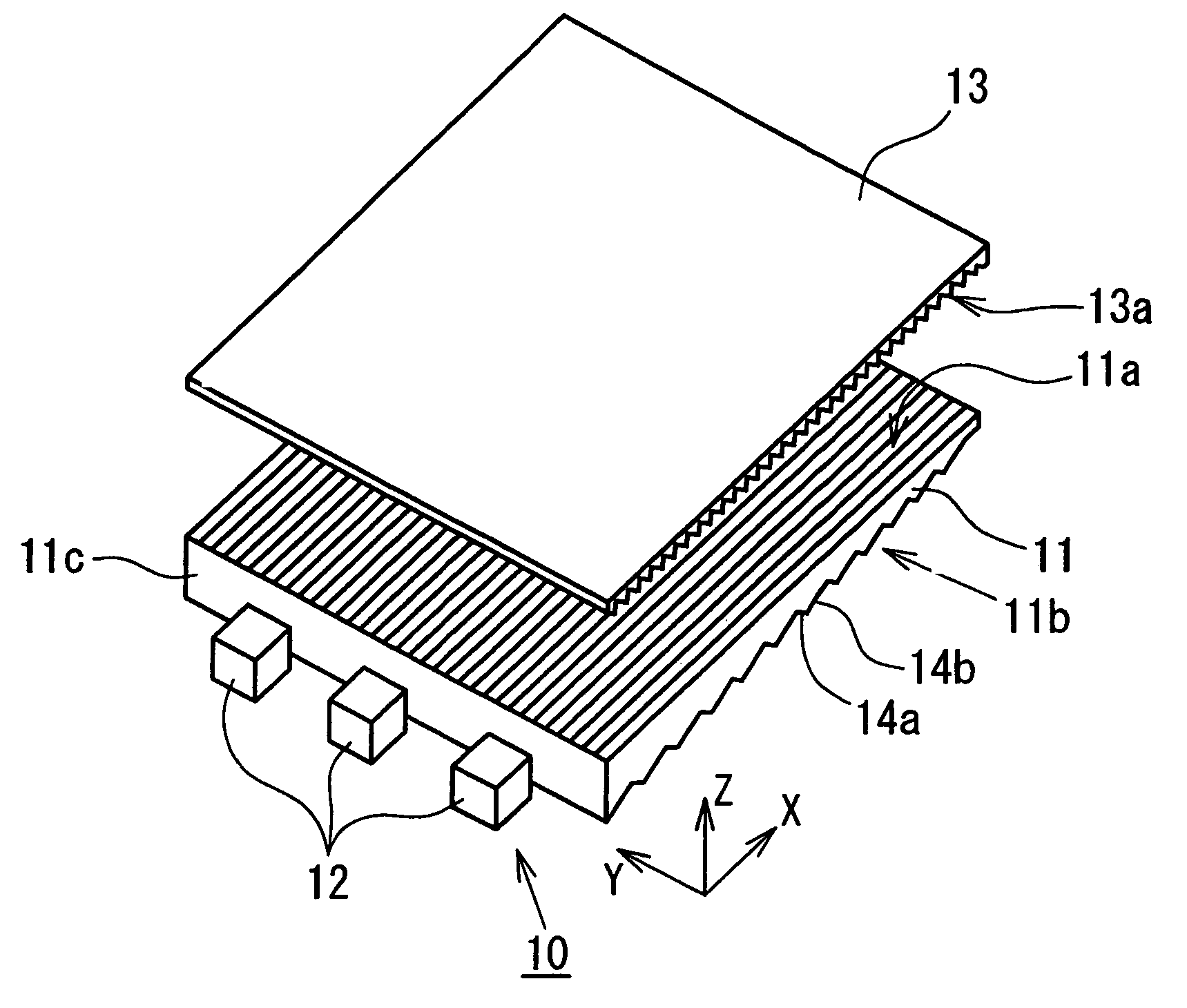
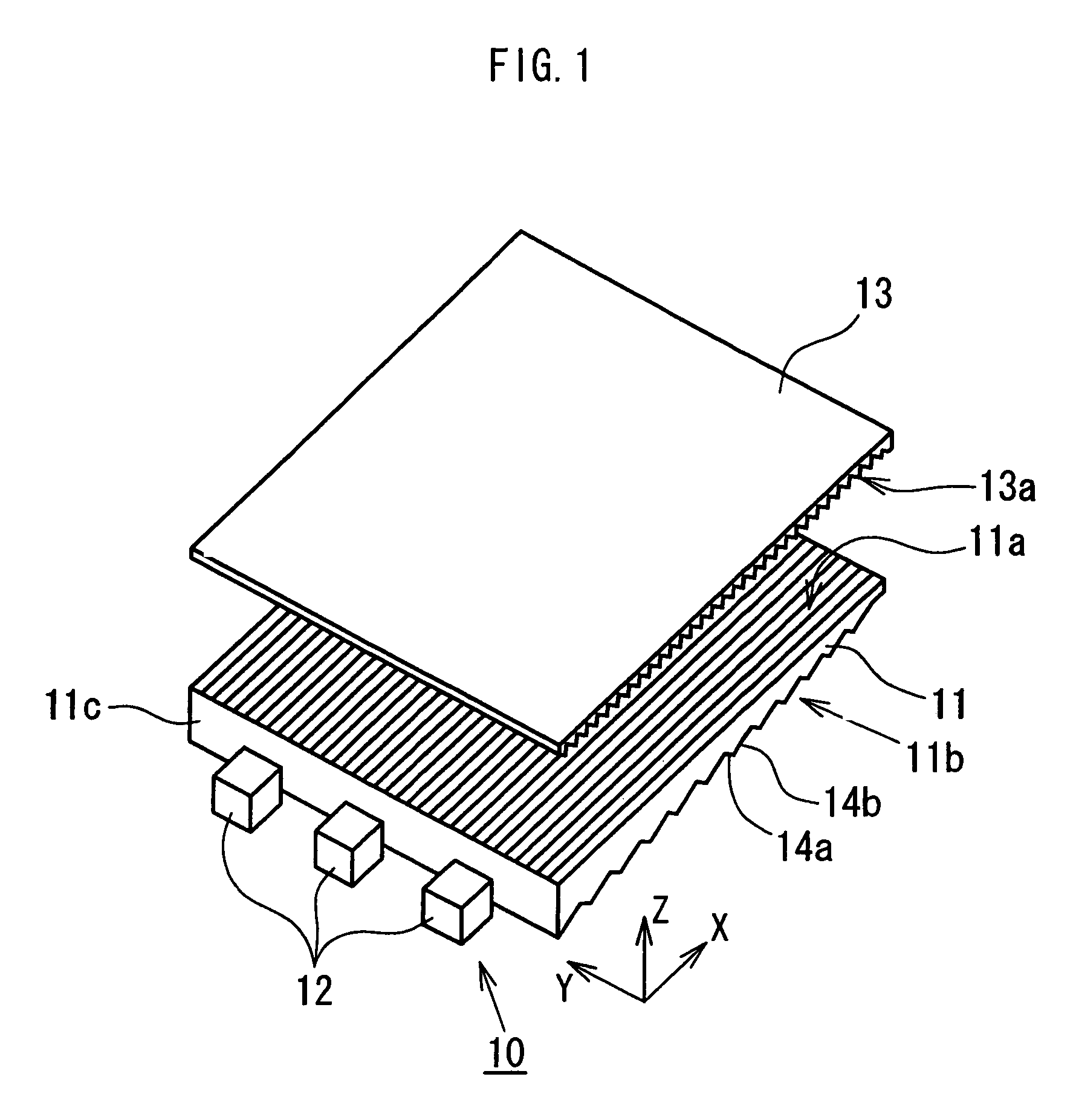
[0034]A first embodiment will hereinafter be described with reference to FIGS. 1 to 4B. Referring to FIG. 1, a spread illuminating apparatus 10 comprises a light conductive plate 11, a plurality (three in the figure) of point light sources 12, and a prism sheet 13. The point light sources 12 are white LED's, and the light conductive plate 11 is formed of a transparent resin material, such as methacrylate resin, polycarbonate resin, polystyrene resin, polyolefin resin, amorphous polyolefin resin, polyester resin, transparent fluorocarbon resin, and epoxy resin. The prism sheet 13 is composed of, for example, a PET film based material, and defines a prism surface 13a provided with a plurality of prisms which are formed of methacrylate resin, polycarbonate resin, or the like, have a triangular cross section, and which extend in one same direction.

[0035]In the spread illuminating apparatus 10, the point light sources 12 are disposed parallel to a light entrance surface 11c of the light ...

second embodiment

[0051]In the light conductive plate 41 shown in FIG. 5A, the distances W1 to WN−1 between the apexes of the triangular prisms T1 to TN are arranged irregularly. Referring now to FIG. 6 showing a modification of the second embodiment described above, a light conductive plate 51 shown in the YZ section has a plurality of triangular prisms divided into a plurality of units L repeatedly arrayed, each of which is composed of a plurality (three in the figure) of different triangular prisms T1, T2 and T3 defining different distances W1 and W2 between their respective apexes. A dimension between the apexes of two abutting prisms of two adjacent units L is defined as a distance d, and respective distances d may be equal to one another or may alternatively differ from one another in a regular or irregular manner. The number of triangular prisms constituting the unit L, and the distance between the apexes of the prisms are appropriately set in consideration of brightness distribution uniformit...

third embodiment

[0053]the present invention will be described with reference to FIGS. 8A to 10B. A spread illuminating apparatus according to the third embodiment includes the same components as illustrated in FIG. 1 except a light conductive plate, and therefore an illustration thereof is omitted. In explaining the third embodiment, any component parts corresponding to those in FIG. 1 are denoted by the same reference numerals except the light conductive plate and its relevant portions.

[0054]FIG. 8A is a cross-sectional view (partly omitted) of a light conductive plate 71 taken along a line parallel to a light entrance surface 71c thereof (YZ section), and FIG. 8B is an enlarged view of a portion of the cross section shown in FIG. 5A. Referring to FIG. 8A, the light conductive plate 71 has, at a light exit surface 71a thereof, a plurality of polygonal prisms P1 to PN (N is a predetermined positive integer) which have respective different numbers n of sides, have respective different shapes in the ...


PUM

PropertyMeasurementUnit
tangential anglesaaaaaaaaaa
distancesaaaaaaaaaa
surface roughnessaaaaaaaaaa

Abstract

A side light type spread illuminating apparatus comprises: a light conductive plate having a plurality of prisms formed on a light exit surface thereof, point light sources; and a prism sheet disposed on the light conductive plate, wherein the prisms have respective circular arc configurations with a common curvature in cross section taken along a line orthogonal to the direction the prisms extend, and are arrayed such that distances each defined between apexes of adjacent two of the prisms differ irregularly from one another within a range of 10 to 200 μm, and such that overall tangential angles at respective ends of the prisms vary irregularly within a range of 40 to 70 degrees, and wherein the respective ridges of the prisms are located on a common virtual plane, whereby the prism sheet are supported evenly by all of the prisms of the light conductive plate.

Description

BACKGROUND OF THE INVENTION[0001]1. Field of the Invention[0002]The present invention relates to a spread illuminating apparatus as a lighting means for a liquid crystal display apparatus, and more specifically to a side light type illuminating apparatus using a point light source.[0003]2. Description of the Related Art[0004]Recently, a liquid crystal display (hereinafter referred to as “LCD” as appropriate) apparatus is extensively used as a display device for electronic equipments, such as personal computers, cellular phones, and the like. Since the liquid crystal, unlike a cathode ray tube, does not emit light by itself, a transmission type LCD apparatus requires a lighting means for illuminating its liquid crystal panel, and also a semi-transmission type LCD apparatus which utilizes outside light must have an auxiliary lighting means for enabling a usage in the dark. A side light type illuminating apparatus mainly comprises a light conductive plate and a light source disposed at...

Claims


Application Information

Patent Timeline
Patent Type & Authority Patents(United States)
IPC IPC(8): F21V7/04G02B6/00F21V8/00F21Y101/02G02F1/13357
CPCG02B6/0038G02B6/0053G02F1/133615
Inventor KUNIMOCHI, TORU
Owner MINEBEAMITSUMI INC
Why Eureka
Try Eureka