Channel power balancing in a multi-channel transceiver system

a transceiver system and power balancing technology, applied in the field of high data rate transmission of data, can solve the problems of inefficient bandwidth, difficult to increase the data rate across the bus b>110, and conventional networking environments operate at slower baud rate, and achieve the effect of high data transmission ra

Active Publication Date: 2007-07-24
ENTROPIC COMM INC
View PDF12 Cites 14 Cited by
  • Summary
  • Abstract
  • Description
  • Claims
  • Application Information

AI Technical Summary

Benefits of technology

[0014]In accordance with the present invention, a transceiver is presented that allows very high data transmission rates over a data bus that is less susceptibl

Problems solved by technology

One of the biggest problems with existing SERDES systems 100 is that they are very bandwidth inefficient, i.e., they require 3.125 GHz of bandwidth to transmit and receive 2.5 Gbps of data over a single pair of copper wires.
Therefore, it is very difficult to increase the data rates across bus 110.
Conventional networking environments operate at slower baud rates, but suffer from similar difficulties.
Therefore, the higher the data rate the more I

Method used


Image

  • Channel power balancing in a multi-channel transceiver system
  • Channel power balancing in a multi-channel transceiver system
  • Channel power balancing in a multi-channel transceiver system

Examples


Embodiment Construction

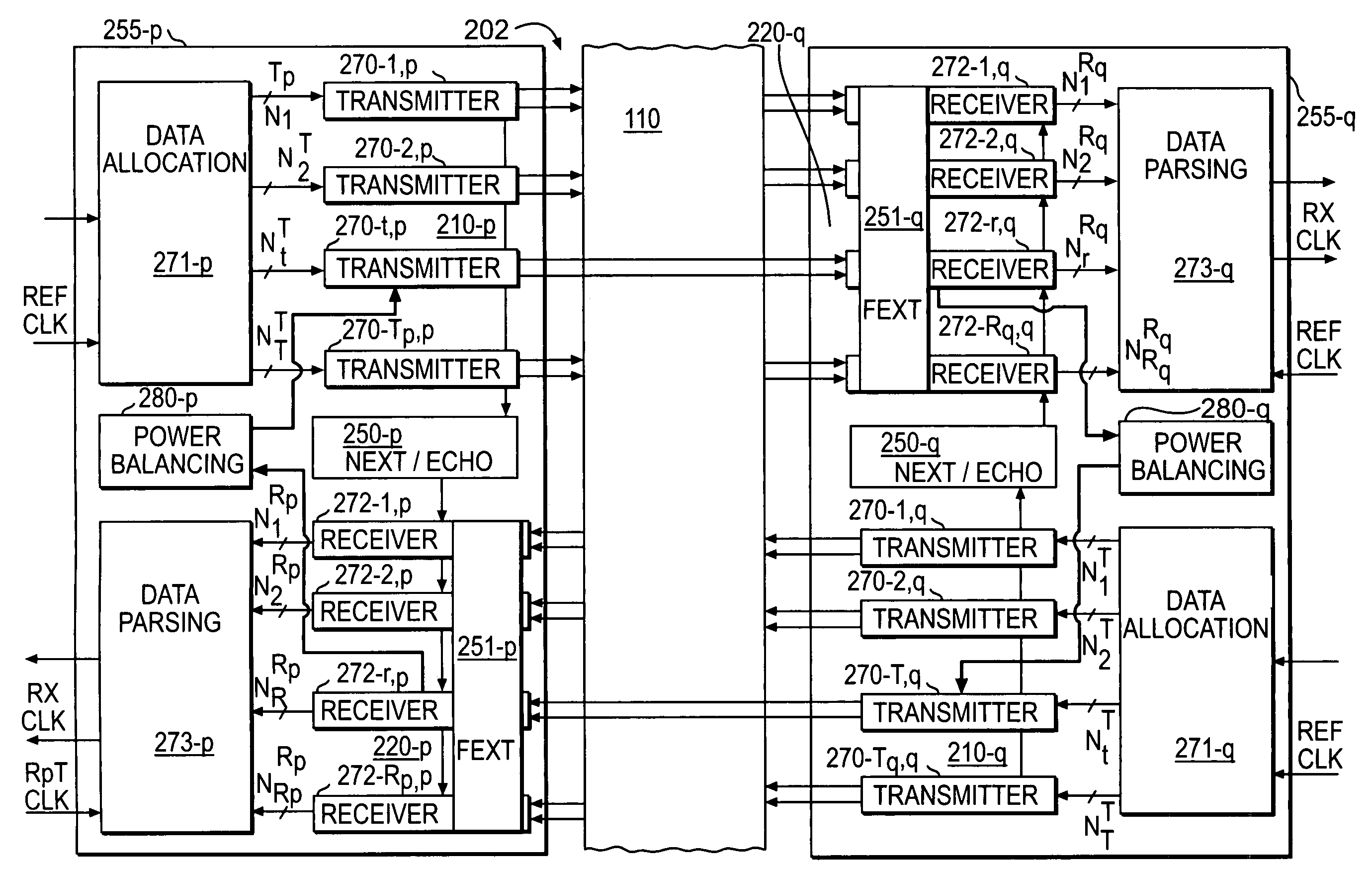
[0031]FIG. 2A shows a block diagram of a transmission system 200 according to the present invention. System 200 includes any number of components 201-1 through 201-P, with component 201-p representing an arbitrary one of components 201-1 through 201-P, coupled through a transmission medium 110. Transmission medium 110 may couple component 201-p to all of the components 201-1 through 201-P or may couple component 201-p to selected ones of components 201-1 through 201-P. In some embodiments, individual transmitters and receivers of components 201-1 through 201-P are coupled together through category 5, 5E or 6 twisted copper pair.

[0032]Examples and details of aspects of multi-channel transceivers in addition to those presented here are described in U.S. application Ser. No. 10 / 454,382, “Near-End, Far-End and Echo Cancellers in a Multi-Channel Transceiver System” filed on Jun. 3, 2003 by Sreen A. Raghavan Thulasinath G. Manickam Peter J. Sallaway Gerard E. Taylor; U.S. application Ser....


PUM


Abstract

A transceiver according to some embodiments of the present invention receives data from a plurality of frequency separated transmission channels from a complementary transmitter of another transceiver and adjusts the power output of certain channels in a transmitter of the receiver. Upon start-up, the power output levels of signals in individual channels in the transmitter can be preset. A power balance can determine new power output levels of the transmitter from parameters in the receiver while receiving data transmitted by a similarly situated complementary transmitter in a second transceiver coupled to the transceiver. In some embodiments, a complementary receiver of the other transceiver determines the power outputs of the transmitter and the power levels are transmitted to the transmitter by the other transceiver.

Description

BACKGROUND[0001]1. Field of the Invention[0002]The present invention is related to high-speed communications of data in a communication system and, in particular, to high data rate transmission of data between components in a communication system.[0003]2. Discussion of Related Art[0004]There is currently a great deal of interest in high speed transceiver systems, both for communications in an intranet environment and for communications between components in various systems. As an example of a high data rate system, high-speed Ethernet local area networks (LANs), 100 BASE-TX Ethernet and 1000 Base TX Ethernet (1 Gigabit / s) using category-5, 5E or 6 copper wire, are being developed. These high speed systems require new techniques in high-speed data processing. High-speed data transmission techniques are also useful in wide-area networks and digital subscriber loop applications. High data rate transceiver systems are also utilized in many back-plane environments, including optical swit...

Claims


Application Information

Patent Timeline
IPC IPC(8): H04B7/00H04Q7/20H04W52/42
CPCH04L25/14H04L27/2602H04W52/42
Inventor RAGHAVAN, SREEN A.MANICKAM, THULASINATH G.SALLAWAY, PETER J.TAYLOR, GERARD E.
Owner ENTROPIC COMM INC
Why Eureka
Try Eureka