Thermal generator and combustion method for limiting nitrogen oxides emissions by re-combustion of fumes

a technology of nitrogen oxides and generators, which is applied in the direction of combustion types, lighting and heating apparatus, combustion using lumps and pulverizing fuel, etc., can solve the problems of reducing the overall energy efficiency, requiring more sophisticated and expensive automatic cleaning equipments, and presenting considerable drawbacks. , to achieve the effect of reducing operating conditions and facilitating control of heat extraction

Inactive Publication Date: 2007-07-31
INST FR DU PETROLE
View PDF28 Cites 2 Cited by
  • Summary
  • Abstract
  • Description
  • Claims
  • Application Information

AI Technical Summary

Benefits of technology

[0035]The invention thus provides a simple, efficient and safe solution for recombustion of boiler fumes allowing to significantly reduce emissions of pollutants and in particular of nitrogen oxides (NOx).
[0050]Advantageously, the solution provided in the present application to significantly reduce the NOx emissions level in the fumes finally discharged can also be applied to boilers equipped with vertical cylindrical furnaces, whether flash boilers or not. It is also applicable to water-tube boilers having cylindrical or parallelepipedic furnaces.

Problems solved by technology

Although in its principle recombustion is attractive as regards performances and insofar as it requires no reactant allowing to reduce the nitrogen oxides other than the fuel itself, it however presents considerable drawbacks.
high corrosion in the recombustion zone and in the postcombustion zone, due to the presence of a reducing atmosphere or to alternating oxidizing and reducing atmospheres,
imperfect oxidation of the recombustion fuel in the postcombustion zone and, as a consequence, formation of gaseous and solid unburnt residues and, in the most severe cases, fouling of the downstream exchange surfaces, which reduces the overall energy efficiency and requires more sophisticated and expensive automatic cleaning equipments,
safety difficult to provide because of the stage of injection of a fuel in the recombustion zone.
The main risk is a non-combustion of said fuel owing to an operating trouble or to an ill-controlled transient operation.
In this case, there are risks of explosion in the parts situated downstream from the recombustion zone (recovery boiler, filter, etc.).
In the case of a thermal generator working with heavy petroleum products, the implementation difficulties are the same as those encountered with natural gas, but they are often increased for some of them.
Furthermore, the denitrification efficiency can be lower with these heavy products because of the presence of nitrogen-containing compounds in the initial fuel.

Method used


Image

  • Thermal generator and combustion method for limiting nitrogen oxides emissions by re-combustion of fumes
  • Thermal generator and combustion method for limiting nitrogen oxides emissions by re-combustion of fumes

Examples


Embodiment Construction

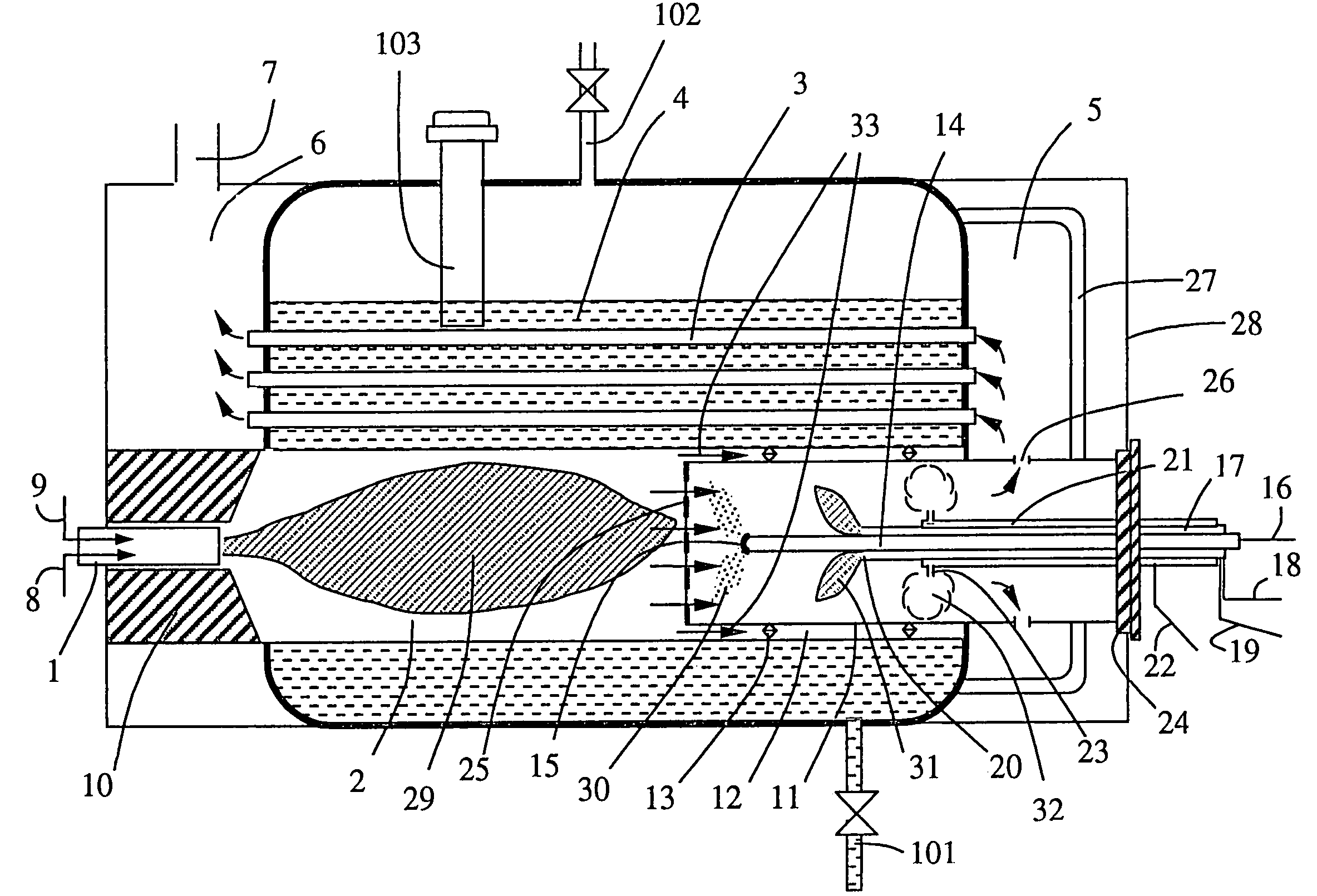
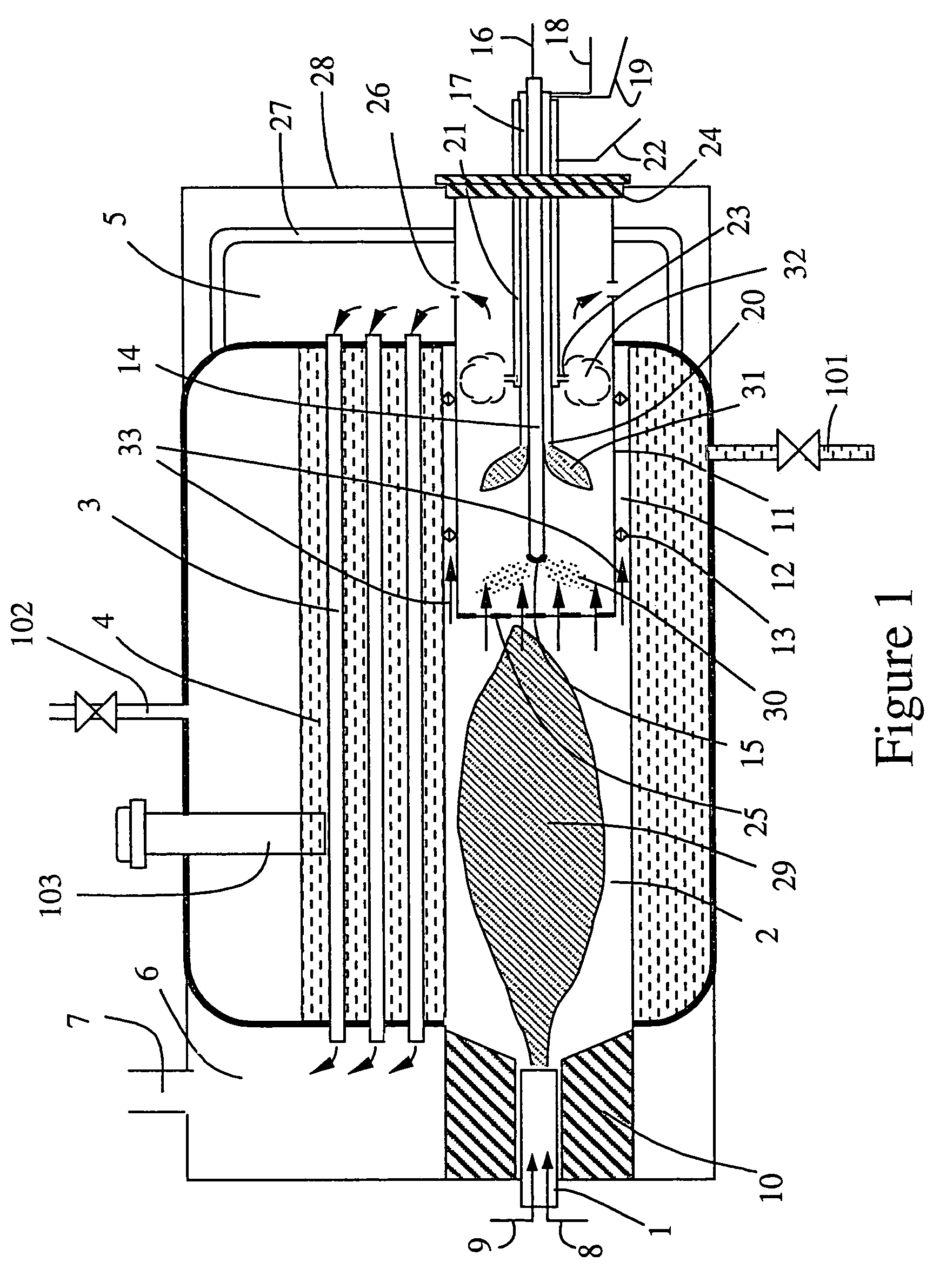
[0052]FIG. 1 shows an industrial two-pass fumes-tube boiler including a recombustion device according to the invention but, of course, the invention is not restricted to this type of boiler configuration.

[0053]The boiler comprises a burner 1, a cylindrical furnace tube 2, fumes tubes 3 used as recovery means for the heat of the fumes resulting from combustion, a cylindrical boiler barrel 4 wherein the water to be heated and vaporized is contained, fumes boxes 5 and 6, a smokestack 7, a water inlet 101, a steam outlet 102 and a device 103 intended for water level control in said boiler barrel 4.

[0054]Burner 1 is supplied, through line 8, with a gaseous or liquid fuel and with an oxidizer, here in form of a gas which may be air, through line 9. This burner is placed in a quarl 10 and it produces a flame 29 which develops in furnace tube 2 of substantially cylindrical shape and heats the water present around this furnace tube.

[0055]Furnace tube 2 is designed in such a way that, at full...


PUM


Abstract

The invention relates to a thermal generator comprising a furnace tube (2) wherein a fuel is burnt, recombustion means (14, 15) for reducing the nitrogen oxides content present in said fumes and means (3) for recovering the heat of the fumes resulting from said combustion. The invention is characterized in that recombustion means (14, 15) are arranged in containment means (11).

Description

FIELD OF THE INVENTION[0001]The present invention relates to the sphere of thermal generators, notably industrial boilers, allowing to limit nitrogen oxides emissions by recombustion of the fumes and to a method for implementing such a generator.[0002]The invention is applicable to any type of boiler such as, for example, fume-tube boilers, water-tube boilers, ambitubular boilers, and it can be implemented whatever the thermal power of said boiler.BACKGROUND OF THE INVENTION[0003]There are well-known methods for recombustion of the fumes discharged so as to reduce the NOx emissions, such as those described in patents U.S. Pat. No. 5,139,755 and WO97 / 25,134.[0004]This recombustion is a nitrogen oxides reduction technique based on stepping of the combustion. A furnace usually contained in these boilers, wherein this technique is used, comprises three zones:[0005]the first zone wherein about 85 to 95% by mass of the fuel is burnt under standard conditions, i.e. with about 5 to 15% exce...

Claims


Application Information

Patent Timeline
Patent Type & Authority Patents(United States)
IPC IPC(8): F23C6/04F23C5/00F23C5/02F23C5/08F23M9/06
CPCF23C6/042F23M9/06F23C2201/30
Inventor MARTIN, GERARDNASTOLL, WILLYROESLER, JOHN
Owner INST FR DU PETROLE
Why Eureka
Try Eureka