Method for manufacturing liquid ejection head

Inactive Publication Date: 2007-07-31
CANON KK
View PDF16 Cites 26 Cited by
  • Summary
  • Abstract
  • Description
  • Claims
  • Application Information

AI Technical Summary

Benefits of technology

[0015]An object of the present invention is to provide a method for manufacturing a liquid-ejection head high in accuracy and in reliability while simplifying the manufacturing process thereof, wherein, prior to forming a liquid supply port passing through an insulating layer by the etching starting from a rear surface side of a s

Problems solved by technology

However, since a resistivity of polysilicon is generally high, it is necessary to lower the resistivity when used as the gate electrode of the transistor, for example, by doping impurity.
On the other hand, since an etching speed of polysilicon doped with impurity is liable to lower, it is unsuitable for using polysilicon as a material for the sacrificial layer which needs the etching speed higher than that of a material to be etched.
Further, since the

Method used


Image

  • Method for manufacturing liquid ejection head
  • Method for manufacturing liquid ejection head
  • Method for manufacturing liquid ejection head

Examples


first embodiment

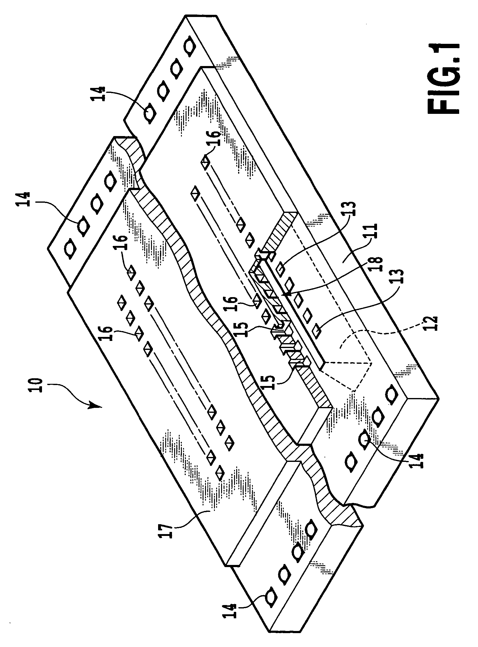
[0070]A structure of a printing element substrate 10 in a printing head is shown in FIG. 1. In the printing element substrate 10, ejection energy generators, liquid chambers, ejection openings or others are formed on a silicon substrate 11 of 0.5 to 1 mm thick.

[0071]In the silicon substrate 11, a liquid supply port 12 of an elongate hole shape is formed to pass through the same. On opposite sides of the liquid supply port 12, a plurality of electro-thermal transducers 13 are arranged at a predetermined gap in a lengthwise direction of the liquid supply port 12 while shifting half a pitch from one on the opposite side, whereby the ejection energy generator is constituted. In the silicon substrate 11, other than the electro-thermal transducers 13, there are electrode terminals 14 for electrically connecting the electro-thermal transducers 13 to a printer body and electric wiring not shown made, for example, of aluminum, both of which are formed by the deposition technique. A drive si...

second embodiment

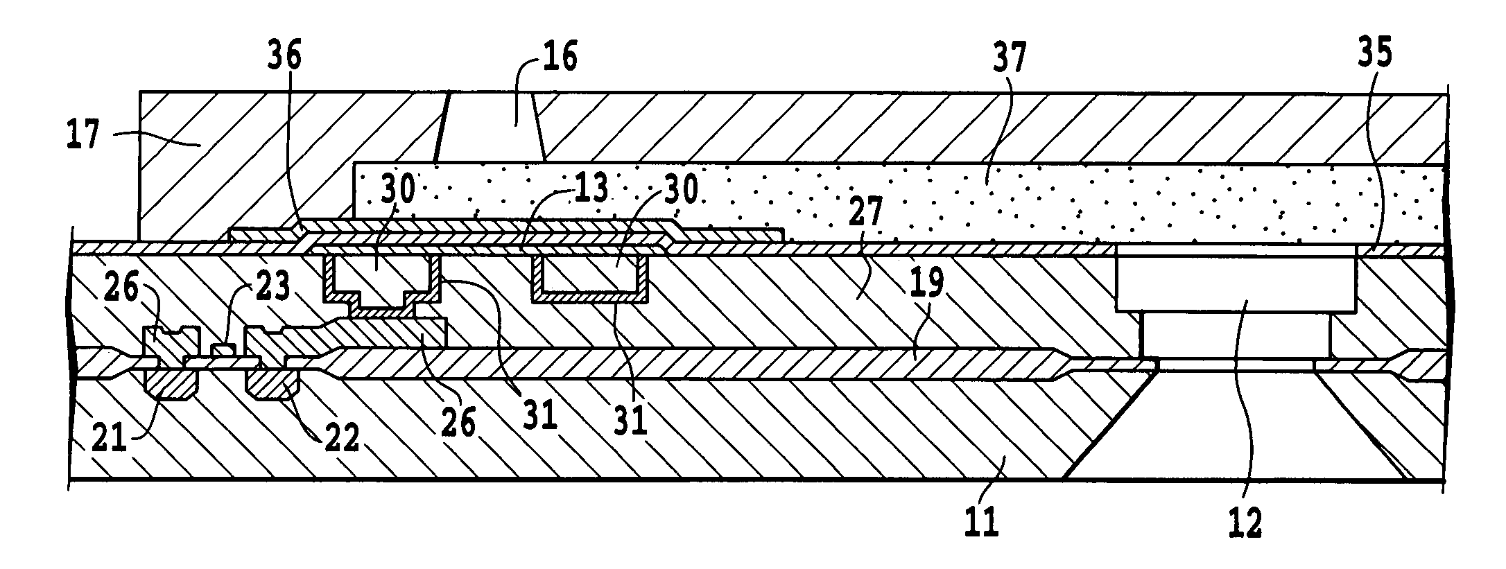
[0091]Such the present invention will be described with reference to FIGS. 10 to 13, wherein parts having the same functions as in the preceding embodiment are indicated by the same reference numerals and the redundant explanation thereof are eliminated. That is, while the etching-stop layer 32 is solely brought into contact with the upper end surface of the sacrificial layer 20 in the preceding embodiment, the etching-stop layer 32 extends to the SiO2 layer 19 to cover the sacrificial layer 20 according to this embodiment (see FIG. 10). Thereby, it is possible to completely shut the insulating layer 27 from the sacrificial layer 20.

[0092]Thus, in a state shown in FIG. 10, when the liquid supply port 12 reaching the sacrificial layer 20 is formed by the anisotropic etching carried out on the rear surface of the silicon substrate 11, the invasion of the etching liquid upon the insulating layer 27 is completely prevented since the insulating layer 27 is separated from the sacrificial ...

third embodiment

[0095]Then, the present invention is described with reference to FIGS. 14 to 18. In this case, to avoid the redundancy, the liquid supply port 12 will be solely described. In these drawings, parts having the same functions as in the preceding embodiments are indicated by the same reference numerals. That is, after the SiO2 layer 19 is formed on the silicon substrate 11 and the PSG layer 38 is formed thereon by the cold CVD method, portions of the SiO2 layer 19 and the PSG layer 38 in which the liquid supply port 12 is to be formed are simultaneously removed by the etching to form an opening 39, to which is exposed the silicon substrate 11 (see FIG. 14).

[0096]Next, the electrode wiring layer 26 of aluminum-copper alloy (see FIG. 4) is formed on the PSG layer 38 and patterned to have a predetermined shape. At this stage, the driver elements such as a drive transistor or others described hereinabove is completed.

[0097]Then, the SiO2 insulating layer 27 of 1.0 to 1.8 μm thick is deposit...


PUM

PropertyMeasurementUnit
Pressureaaaaaaaaaa
Energyaaaaaaaaaa
Tensile stressaaaaaaaaaa

Abstract

A method for manufacturing a liquid ejection head having a substrate including an electro-thermal transducer for ejecting a liquid from an ejection opening, an electrode wiring section electrically connecting the electro-thermal transducer and driver element thereof, and a liquid supply port therethrough includes the steps of forming a sacrificial layer by using the same material as the electrode wiring section at a position at which the liquid supply port is to be formed during forming the electrode wiring section, forming an anti-etching layer covering the sacrificial layer, removing the sacrificial layer by etching the substrate from a surface thereof opposite to the surface on which the electro-thermal transducer is formed to expose the anti-etching layer of a portion to be the liquid supply port, and removing the exposed anti-etching layer to form the liquid supply port in the substrate.

Description

[0001]This application claims priority from Japanese Patent Application Nos. 2003-178549 filed Jun. 23, 2003 and 2004-163739 filed Jun. 1, 2004, which are incorporated hereinto by reference.BACKGROUND OF THE INVENTION[0002]1. Field of the Invention[0003]The present invention relates to a method for manufacturing a liquid ejection head capable of simplifying the manufacturing process and excellent in reliability.[0004]In this Specification, a word “print” refers to not only forming a significant information, such as characters and figures, but also forming images, designs or patterns on a printing medium and processing such as etching and so forth in the printing medium, whether the information is significant or insignificant or whether it is visible so as to be perceived by humans. The term “printing medium” includes not only paper used in common printing apparatus, but also sheet materials such as cloths, plastic films, metal sheets, glass plates, ceramic sheets, wood panels and le...

Claims


Application Information

Patent Timeline
IPC IPC(8): B41J2/04H01L21/00B41J2/16B41J2/05
CPCB41J2/1603B41J2/1629B41J2/1632B41J2/1639B41J2/1642B41J2/1635Y10T29/49401B41J2202/13B41J2/16
Inventor KOMURO, HIROKAZUMUROOKA, FUMIO
Owner CANON KK
Why Eureka
Try Eureka