Dual frequency band wireless LAN

a dual-band wireless and lan technology, applied in the field of dual-band wireless lan devices, can solve the problems of increasing the size and cost of the solution, slow and expensive development of the chipset, and achieve the effect of cost saving and low cos

Inactive Publication Date: 2007-07-31
QUALCOMM INC
View PDF29 Cites 67 Cited by
  • Summary
  • Abstract
  • Description
  • Claims
  • Application Information

AI Technical Summary

Benefits of technology

[0008]The present inventors have realized the need for an integrated, low cost wireless LAN solution that can accommodate a plurality of modes of operation. The present invention provides a dual band transceiver that is constructed without the need for two independent and complete transceiver systems, while also providing the option of single band operation and cost savings. Various implementations of chipsets for both radios and supporting circuitry are provided on a PC board (or otherwise integrated into other components) that allow the construction of a dual mode, dual band wireless WLAN solution.
[0009]The present invention includes an approach to dual band design that is neither in two complete and independent radio systems, nor does it require entirely new development. The present invention utilizes some existing radio components in a new way that reduces additional design work to produce a new product. The preferred embodiment of the present invention includes a 5 GHz OFDM design modified by the addition of a uniquely arranged frequency conversion stage that supports 2.4 GHz operation. The result is rapid time to market with a solution that is lower cost and size than an approach using two independent chipsets.

Problems solved by technology

This increases the size and cost of the solution.
However, since such integrated solutions require the development of completely new silicon for all modes of operation, the development of these chipsets is slow and expensive.

Method used


Image

  • Dual frequency band wireless LAN
  • Dual frequency band wireless LAN
  • Dual frequency band wireless LAN

Examples


Embodiment Construction

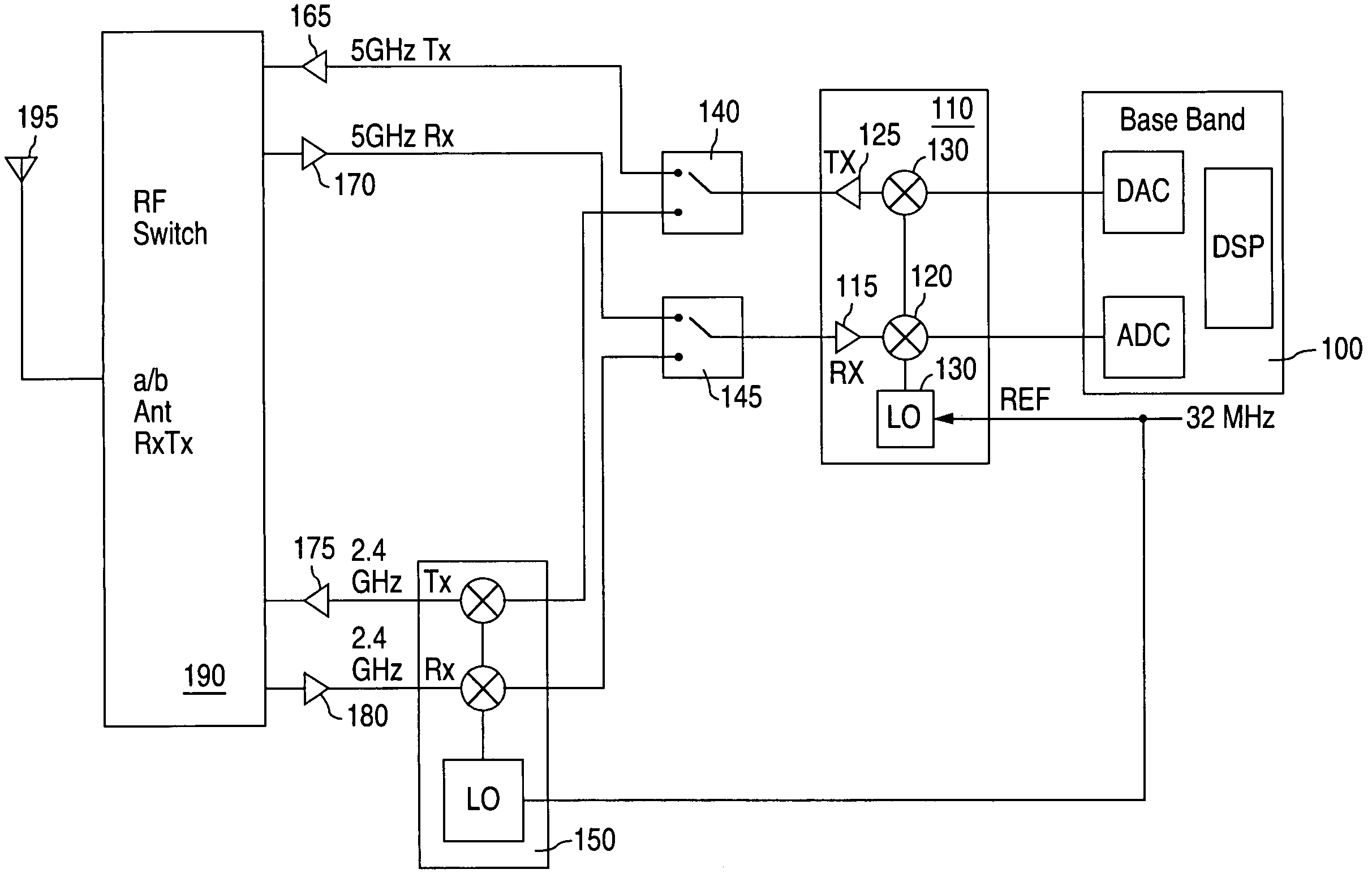
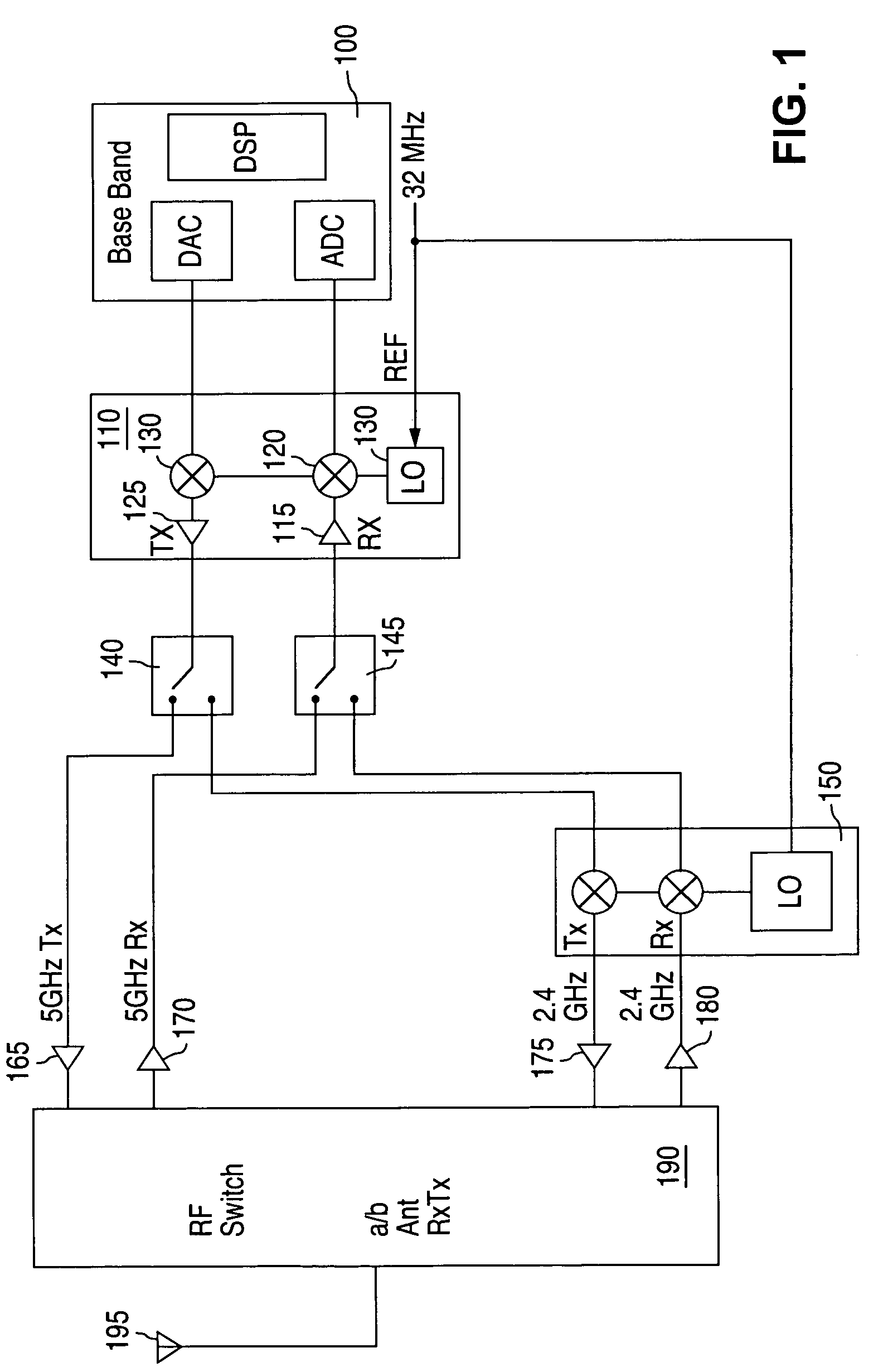
[0024]Referring now to the drawings, wherein like reference numerals designate identical or corresponding parts, and more particularly to FIG. 1 thereof, there is illustrated a top level block diagram of a dual band transceiver according to an embodiment of the present invention. A base band processor 100 processes signals that are to be broadcast and signals that are received. A first RF device 110 converts signals that are to be broadcast to a first RF frequency band. In a preferred embodiment, the first RF frequency band is the 5 GHz frequency band, and the first RF device 110 is a radio on a chip (e.g., the AR5111 chip from Atheros Communications, Inc., assignee of the present invention). However, other 5 GHz (or other first RF frequency) chip sets or discrete components may be utilized.

[0025]Switch 140 routes the first RF frequency band signals to RF circuitry including PA 165, switches (e.g. 11a / 11b (also called “a / b” herein) antenna switch, and RxTx switch) 190, and on-chip f...


PUM


Abstract

A dual band radio is constructed using a primary and secondary transceiver. The primary transceiver is a complete radio that is operational in a stand alone configuration. The secondary transceiver is a not a complete radio and is configured to re-use components such as fine gain control and fine frequency stepping of the primary transceiver to produce operational frequencies of the secondary transceiver. The primary transceiver acts like an intermediate frequency device for the secondary transceiver. Switches are utilized to divert signals to / from the primary transceiver from / to the secondary transceiver. The switches are also configured to act as gain control devices. Antennas are selected using either wideband or narrowband antenna switches that are configured as a diode bridge having high impedance at operational frequencies on control lines that bias the diodes.

Description

COPYRIGHT NOTICE[0001]A portion of the disclosure of this patent document contains material which is subject to copyright protection. The copyright owner has no objection to the facsimile reproduction by anyone of the patent document or the patent disclosure, as it appears in the Patent and Trademark Office patent file or records, but otherwise reserves all copyright rights whatsoever.BACKGROUND OF THE INVENTION[0002]1. Field of Invention[0003]The present invention relates to wireless devices and access systems, and amongst other things to a dual frequency wireless LAN device and techniques for constructing the wireless LAN device.[0004]2. Discussion of Background[0005]Multi-band radios are available in a number of industries. In particular, the cell phone industry has utilized dual band and tri-band radios for a number of years. For example, Motorola's StarTac and Qualcomm's 2760 operate on at least two different frequency bands and / or formats.[0006]Currently there are two particul...

Claims


Application Information

Patent Timeline
Patent Type & Authority Patents(United States)
IPC IPC(8): H03C7/02H03H7/01H03H7/48H04B7/06H04B7/08H04L12/28
CPCH03H7/0153H03H7/48H04W88/06H04B7/0805H04W84/12H04B7/0602B32B7/12H04H20/33H04L12/28
Inventor MCFARLAND, WILLIAM J.ONEDERA, KEITHSHOR, ARIESU, DAVIDTERROVITIS, MANOLISTHOMSON, JOHNZARAGARI, MASOUD
Owner QUALCOMM INC
Why Eureka
Try Eureka