On-vehicle electronic control device

a technology of electronic control device and vehicle, which is applied in the field of electronic control device of vehicle, can solve the problems of reduced reliability, and increased input/output points of both microcomputers

Active Publication Date: 2007-07-31
MITSUBISHI ELECTRIC CORP
View PDF21 Cites 50 Cited by
  • Summary
  • Abstract
  • Description
  • Claims
  • Application Information

AI Technical Summary

Benefits of technology

[0019]The present invention has been made in order to solve the above-mentioned problems, and therefore has an object to obtain an on-vehicle electronic control device including a concurrent control circuit serially connected to a microprocessor, which subjects the microprocessor allocated to a main part of control to an external diagnosis, thereby improving reliability of performance.
[0021]As described above, the on-vehicle electronic control device according to the present invention includes: the concurrent control circuit that is serially connected to the microprocessor connected to the nonvolatile program memory via the bus; the watchdog timer; the collation information storage unit; the external checksum means; and the interval monitoring means. As a result, external runaway monitoring can be doubly performed on the microprocessor itself by the watchdog timer and the concurrent control circuit. Also, an external checksum can be performed on the nonvolatile program memory functioning in cooperation with the microprocessor. In addition to the external checksum, indirect communication check can be performed as to whether the concurrent control circuit undergoes normal communication or not. Accordingly, improvement is achieved for the reliability of the microprocessor, the nonvolatile program memory, and the concurrent control circuit.

Problems solved by technology

However, according to JP 2001-227402 A, there is a problem of degraded reliability in that an anomaly diagnosis for a program in question is performed based on the self-checking by the program in question per se.
In addition, it is not guaranteed that the checksum is executed on a regular basis.
According to JP 06-259267 A, there is a problem in that mutual transmission of data for a checksum cause an increase of input / output points of both the microcomputers.
In addition, it is not guaranteed that the checksum is executed on a regular basis.
According to JP 05-081222 A, there is a problem in that if a microcomputer is reactivated in response to a reset pulse, a vehicle driver cannot recognize temporal occurrence of runaway of the microprocessor.
However, there is an inconvenience that a temporal malfunction due to noise forces a vehicle into stopping.
All of the conventional techniques as described above have a problem in that cooperation and function allocation are not sufficiently realized when performing runaway monitoring and a checksum for a microprocessor and a program memory, and the functions individually processed fail to guarantee sufficient reliability of performance.

Method used


Image

  • On-vehicle electronic control device
  • On-vehicle electronic control device
  • On-vehicle electronic control device

Examples


embodiment 1

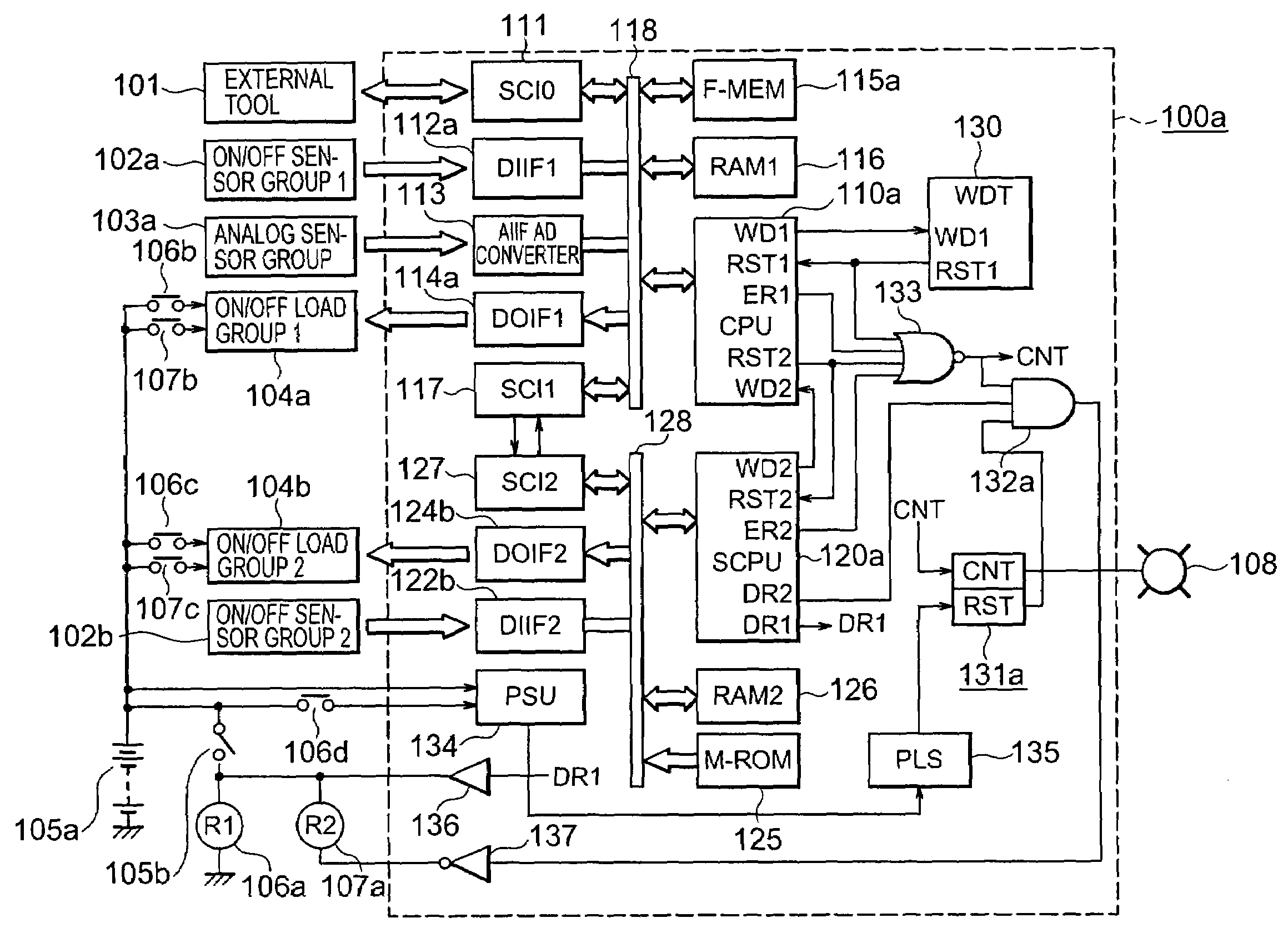
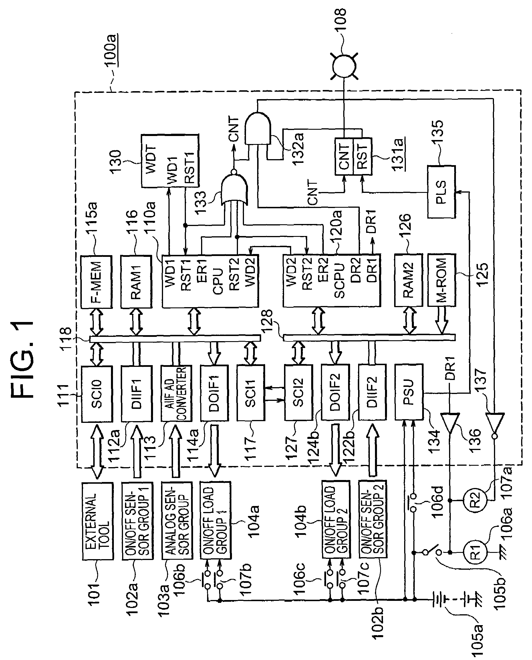
[0031]Hereinafter, referring to FIG. 1, description will be made of an on-vehicle electronic control device according to Embodiment 1 of the present invention.

[0032]FIG. 1 is a block diagram showing an entire configuration of the on-vehicle electronic control device according to Embodiment 1 of the present invention. An on-vehicle electronic control device 100a shown in FIG. 1 is composed of a single electronic circuit board, and received in a hermetically sealed casing.

[0033]First, description is made of components connected to an outside of the on-vehicle electronic control device 100a. An external tool 101 is one of such components connected to the outside. At the time of shipping or maintenance / inspection of a product, the external tool 101 is connected to the on-vehicle electronic control device 100a through a not-shown detachable connector, and transfers and writes a control program and a control constant to a nonvolatile program memory 115a described later.

[0034]In addition, ...

embodiment 2

[0148]Hereinafter, description will be made of components different from those of FIG. 1, based on FIG. 5 that is a block diagram showing an entire configuration of an on-vehicle electronic control device according to Embodiment 2 of the present invention.

[0149]In FIG. 5, an on-vehicle analog sensor group 103b is connected to an on-vehicle electronic control device 100b. Outputs of the on-vehicle analog sensor group 103b are converted into digital values by the multi-channel AD converter 113, and then are inputted to the data bus 118 of a microprocessor 110b via a pair of third serial-parallel converters 140 and 141.

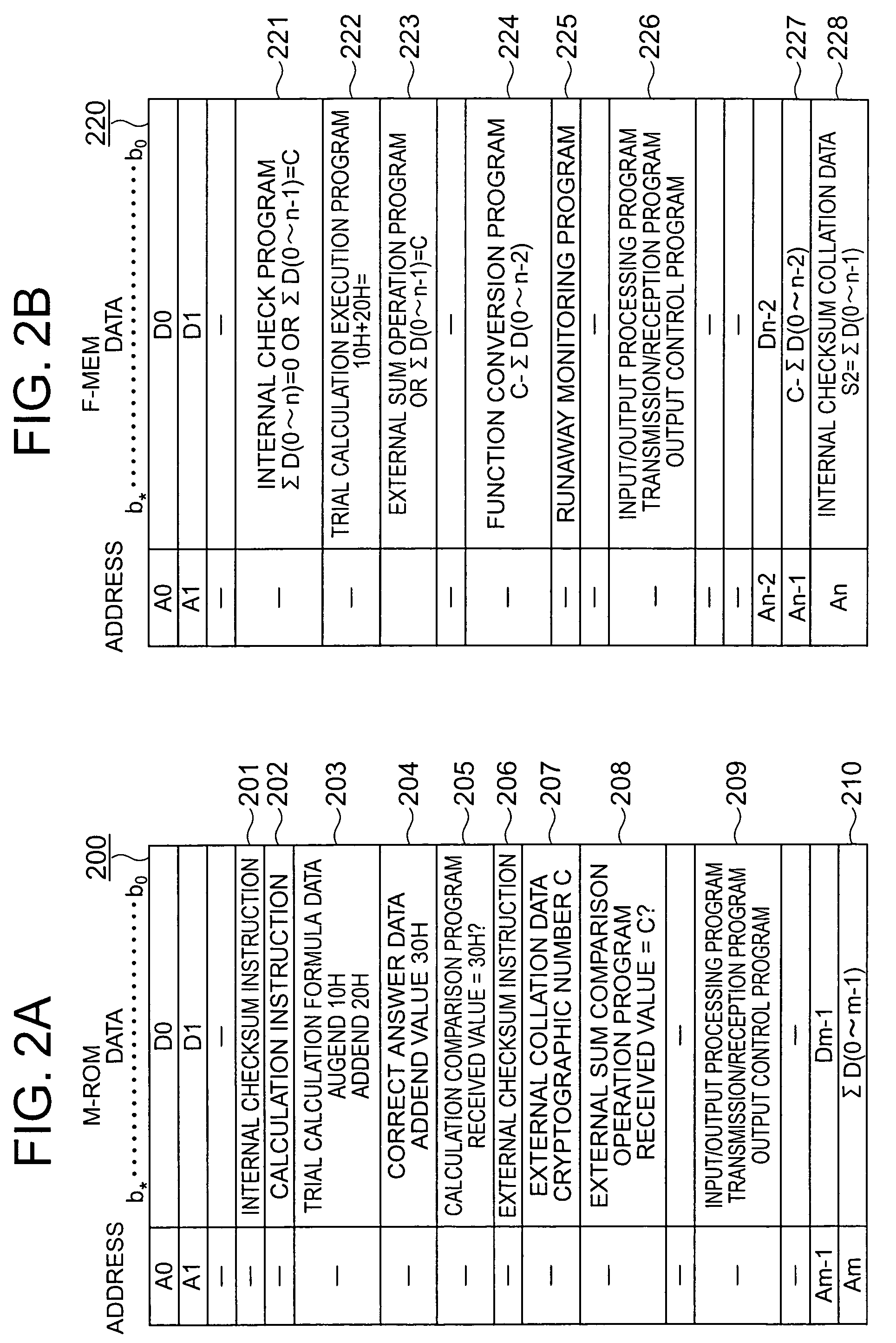
[0150]For example, the microprocessor 110b is composed of a 32-bit microprocessor, and a nonvolatile program memory 115b is composed of a nonvolatile program memory such as a flash memory. The nonvolatile program memory 115b includes the internal checksum program 221, the external checksum program 223, and the programs 226 for the input / output processing, transmission / re...

embodiment 3

[0207]In the on-vehicle electronic control device according to Embodiment 1 shown in FIG. 1, the auxiliary microprocessor is used as the concurrent control circuit. Instead, when the concurrent control circuit does not perform complicated calculation processing, the auxiliary microprocessor may not be used.

[0208]To the contrary, in the on-vehicle electronic control device according to Embodiment 2 shown in FIG. 5, the microprocessor is not used as the concurrent control circuit. Instead, when the concurrent control circuit performs the complicated calculation processing, the auxiliary microprocessor may be used.

[0209]In the on-vehicle electronic control device according to Embodiment 1 shown in FIG. 1, the auxiliary microprocessor has the initiative in the anomaly diagnosis and the microprocessor secondarily operates. Instead, the initiative may be transferred to the microprocessor.

[0210]To the contrary, in the on-vehicle electronic control device according to Embodiment 2 shown in ...


PUM


Abstract

An on-vehicle electronic control device includes an auxiliary microprocessor and subjects a microprocessor allocated to a main part of control to an external diagnosis, thereby improving reliability of performance. A microprocessor including a nonvolatile program memory into which a control program is written is serially connected to an auxiliary microprocessor including an auxiliary nonvolatile program memory. The microprocessor and the auxiliary microprocessor function in cooperation to control on-vehicle electric load groups in response to input signals from on-vehicle sensor groups and on-vehicle analog sensor group. The nonvolatile program memory and the microprocessor are subjected to runaway monitoring performed by a watchdog timer and to an external checksum diagnosis performed periodically by the auxiliary microprocessor. If an anomaly occurs in the runaway monitoring, the external checksum diagnosis, and a checksum interval, parts of electric loads are cut off of power supply by load power relay.

Description

BACKGROUND OF THE INVENTION[0001]1. Field of the Invention[0002]The present invention relates to an on-vehicle electronic control device, for example, an electronic control device incorporating a microprocessor used for performing fuel supply control for a vehicle engine, control of a throttle valve for air supply, or the like.[0003]2. Description of the Related Art[0004]In such an on-vehicle electronic control device as described above, as an anomaly diagnosis for a microprocessor that functions in cooperation with a program memory, runaway of the microprocessor is monitored using a watchdog timer, and program anomalies are monitored using a checksum.[0005]Also, in an on-vehicle electronic control device equipped with an auxiliary microprocessor that is serially connected to the above-mentioned microprocessor and functions in cooperation with the microprocessor, a checksum is also performed on send / receive data in order to check communication data.[0006]Up to now, there is proposed...

Claims


Application Information

Patent Timeline
Patent Type & Authority Patents(United States)
IPC IPC(8): G06F11/00G06F19/00F02P11/00B60R16/02B60W50/02B60W50/04F02D41/22F02D41/26F02D45/00G01M17/007G06F11/10G06F11/30
CPCB60W50/0205B60W50/04F02D41/22F02D41/26G06F11/076
Inventor MITSUEDA, HIROYUKINAKAMOTO, KATSUYAHASHIMOTO, KOHJI
Owner MITSUBISHI ELECTRIC CORP
Why Eureka
Try Eureka