
Method and system for communicating with and tracking RFID transponders

a technology for transponders and transmitters, applied in the field of methods and systems for communicating with and tracking rfid transponders, can solve the problems of affecting the transmission of messages, affecting the overall transponder population, so as to achieve good estimates of the total transponder population

Active Publication Date: 2007-08-07
TERRESTRIAL COMMS LLC
View PDF70 Cites 182 Cited by
  • Summary
  • Abstract
  • Description
  • Claims
  • Application Information

AI Technical Summary

Benefits of technology

"The present invention is an RFID system that includes a host computer and multiple RFID transponders. The host computer sends a unique identification code to each transponder and the transponder generates a random number based on the code. The host computer then sends a message with the unique code to the transponder and the transponder sends its unique code back to the host computer. The host computer uses the unique code to communicate with the transponder. The system also includes an interrogator for transmitting and receiving signals to and from the RFID transponder. The interrogator has multiple antennas and a controller for controlling the transmitter and receiver. The system can be used for identifying and locating RFID transponders in a variety of applications."

Problems solved by technology

As fully described in U.S. Pat. No. 5,530,702 to Palmer et al., a significant difficulty in establishing a multipoint communications system using transponders is how to prevent the transponders from attempting to communicate with the host at the same time.
Such common transmissions usually cause a “collision” among the various transmissions and thereby corrupts the transmitted messages and renders them un-intelligible to the host system.
A problem with this approach, as with any approach utilizing random response delays, is that there must be a good estimate of the total transponder population.
If there are fewer transponders than expected in the field, this approach will spend an unduly long time waiting for responses, while if the population is too great, this method will be contending with large numbers of collisions for long periods of time.
However, as discussed briefly below, each of these systems possesses certain drawbacks in operation that prevent optimum performance.
The '381 Patent discloses an identification system having an interrogator and a plurality of transponders, but requires that the interrogator sequentially transmit two different signals to the transponders using two different antennas, to ensure that all transponders are identified, necessitating additional expense and complexity in the design and construction of the interrogator.
This filtering process, during which no data is recovered by the interrogator, is time intensive when communication is with a large body of transponders.
It is also time intensive because it is limited to only a single transponder response per one or more interrogator commands.
As such, the system of the '570 Patent also provides satisfactory results, but also is time intensive when random wait periods exceed the minimal statistical requirements of the transponder population, and therefore is not optimal.
Although the '603 Patent provides adequate operation, it requires transponders having additional complexity (and therefore additional cost) for the circuitry required to receive transmissions from the other transponders and is also time intensive when faced with a large body of transponders, and thereby presents certain drawbacks.
Another drawback of conventional RFID systems relates to the spatial range between the interrogator and each transponder.
In approving such systems, the FCC has placed strict limitations on the carrier modulation and on the mode of signal returned from the RFID transponder.
The drawbacks of this type of system are that only a single transponder may be addressed at one time and that the spatial distance between the interrogator and the transponder is very small.
These systems operate at ranges up to 6 meters, but are not designed to read more than one transponder.
These systems operate at UHF frequencies (915 MHZ) or microwave frequencies (2.45 GHz or 5.8 GHz) but require complicated frequency hopping circuitry.
The use of a direct sequence spread spectrum (DSSS) signal transmitted from the interrogator to the transponder in RFID systems has been complicated by the need for complex and power intensive demodulation strategies in the transponder.
The system of the '278 Patent is deficient in that it is susceptible to jamming from other on channel carriers, including frequency hopped spread spectrum (FHSS) signals, has long acquisition times (see Column 5, line 60: “.
However, until now the DSSS system and method of the '828 Patent has not been adapted for use in an RFID system.
One problem facing conventional RFID systems is interrogator receiver desensitization caused by the interrogator transmitter itself.
A problem with the pulsed RADAR system was that the power in the transmitted pulse had to be quite high in order for the received signal to have a reasonable signal to noise ratio.
The combination of wide receiver bandwidth to accommodate the short pulse, and the brief integration time for a single pulse, ultimately limited the range of early pulsed RADAR systems.
While this system overcame the need for high peak power, and provided long integration times, it was easily jammed by the presence of other emitters in the band.
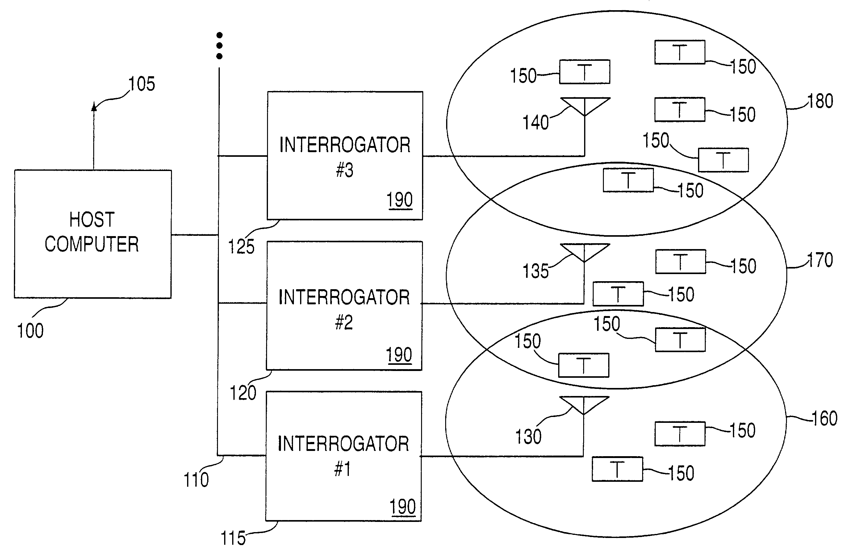
A further problem facing conventional RFID systems is that, in order to read RFID transponders that may be distributed over an area that is considerably larger than the spatial range of a single interrogator antenna assembly, either an interrogator must roam the area or fixed-position interrogators must be positioned in an array located within the area.
However, if adjacent interrogators in such an array are used simultaneously to read data from transponders in the area, their signals might possibly interfere with each other.
If only one interrogator were to be operated at a time, and if each interrogator required several minutes to complete the reading from, or writing to, the RFID transponders within its range, then the entire operation could take several hours to complete.

Method used


Image

  • Method and system for communicating with and tracking RFID transponders
  • Method and system for communicating with and tracking RFID transponders
  • Method and system for communicating with and tracking RFID transponders

Examples


Embodiment Construction

[0043]The present invention is a system and method by which information is written to or read from as many as several thousand arbitrarily located transponders in a spatial range extending to 20 feet or more from each of a plurality of interrogators using radio communications. The present invention provides for the efficient and reliable location and control of very large numbers of transponders, based upon a particular communication protocol and utilizes radar direct sequence range gating and Time Division Multiple Access (TDMA) communications methods. The use of TDMA provides an improvement over the prior art in several ways, including but not limited to: (1) TDMA separates the timing of all responding transponders into discrete intervals (i.e., time slots) such that partial collisions are avoided; and (2) TDMA permits a multiplicity of transponders to be read in each interrogator frame (the collection of time slots comprising the interrogator command time slot and the plurality o...


PUM


Abstract

An RFID system and method for communicating between a host computer, one or more interrogators connected to the host computer, and a large body of transponders distributed within an area covered by the interrogators. Each transponder originally has a common identification code, and upon initialization by the host computer internally generates a unique identification code based upon an internally generated random number. The host, through the interrogators, reads each of the identification codes associated with each transponder by iteratively transmitting a read identification code command along with a controlled variable. Each transponder compares the received controlled variable to an internally generated random number, and selectively transmits its identification code based upon the outcome of this comparison. After the completion of each read identification code iteration, the host adjusts the controlled variable based upon the responses received in the previous iteration. Preferably, communications between the interrogators and the transponders are DSSS signals in TDMA format, and the transponders use the random number generator to assign a time slot for transmission of their response. Each interrogator includes an antenna system utilizing a switch matrix to connect multiple antennas having different polarizations, which ensures that all transponders within the range of the interrogator receive the signals from the interrogator. In a further aspect, the interrogators are arranged in groups, each group in nearest neighbor format, to reduce the time for reading the transponders and the emissions generated when more than one interrogator is active at the same time.

Description

FIELD OF THE INVENTION [0001]The invention relates generally to a system and method for communicating between a host computer and a plurality of RFID transponders (sometimes called tags) through one or more interrogator units, and more specifically to a system and method which greatly reduces the interference caused by transmissions from RFID transponders to those interrogator units, which increases the spatial area available between an interrogator and an RFID transponder and which allows communication between an interrogator and a large body of RFID transponders, among various other advantages. In addition, the invention also relates to a system and method for tracking a large body of RFID transponders in the case where more than one interrogator unit is employed.BACKGROUND OF THE INVENTION[0002]As fully described in U.S. Pat. No. 5,530,702 to Palmer et al., a significant difficulty in establishing a multipoint communications system using transponders is how to prevent the transpo...

Claims


Application Information

Patent Timeline
Patent Type & Authority Patents(United States)
IPC IPC(8): H04Q5/22G06K7/00G06K17/00
CPCG06K7/0008G06K7/10039G06K7/10316G06K7/10356G08B13/2417G08B13/2488G06K2017/007
Inventor ARMSTRONG, JOHN T.RICHERT, JOHN D.PALMER, JOHN P.
Owner TERRESTRIAL COMMS LLC
Learn More