Ingress monitoring system and method

a monitoring system and monitoring method technology, applied in the field of monitoring equipment for use with cable communication networks, can solve the problems of high cost of scanning spectrum analyzers, inability to detect limited, and inability to detect in time, and achieve cost-effective effects

Inactive Publication Date: 2007-08-07
AVANTRON TECH +1
View PDF25 Cites 80 Cited by
  • Summary
  • Abstract
  • Description
  • Claims
  • Application Information

AI Technical Summary

Benefits of technology

[0010]It is therefore a main object of the present invention to provide cost effective system and method for monito

Problems solved by technology

The reverse path data reception can be disturbed by many unwanted ingress sources, that can be either associated with abnormal operation of the network or other sources such as external sources (shortwave transmission, CB transmitter, electrical motors, welding machine, etc.) leaking into the cable or subscriber faulty connection (faulty cable modem, poor grounding, household appliances, etc).
Due to the high cost of scanning spectrum analyzers, a switch is generally used to select one from a plurality of outputs provided on the node receivers for sequential analysis and detection of abnormal conditions by either a single or a limited number of spectrum analyzers.
While spectral analysis can be very sensitive and allow the detection of small incremental differences with averaging, detection is limited to long duration disturbances due to the time-sharing monitoring sequence between receiver outputs and to the scanning nature of spectral analysis.
Although such local detection processing approach may improve detecti

Method used


Image

  • Ingress monitoring system and method
  • Ingress monitoring system and method
  • Ingress monitoring system and method

Examples


Embodiment Construction

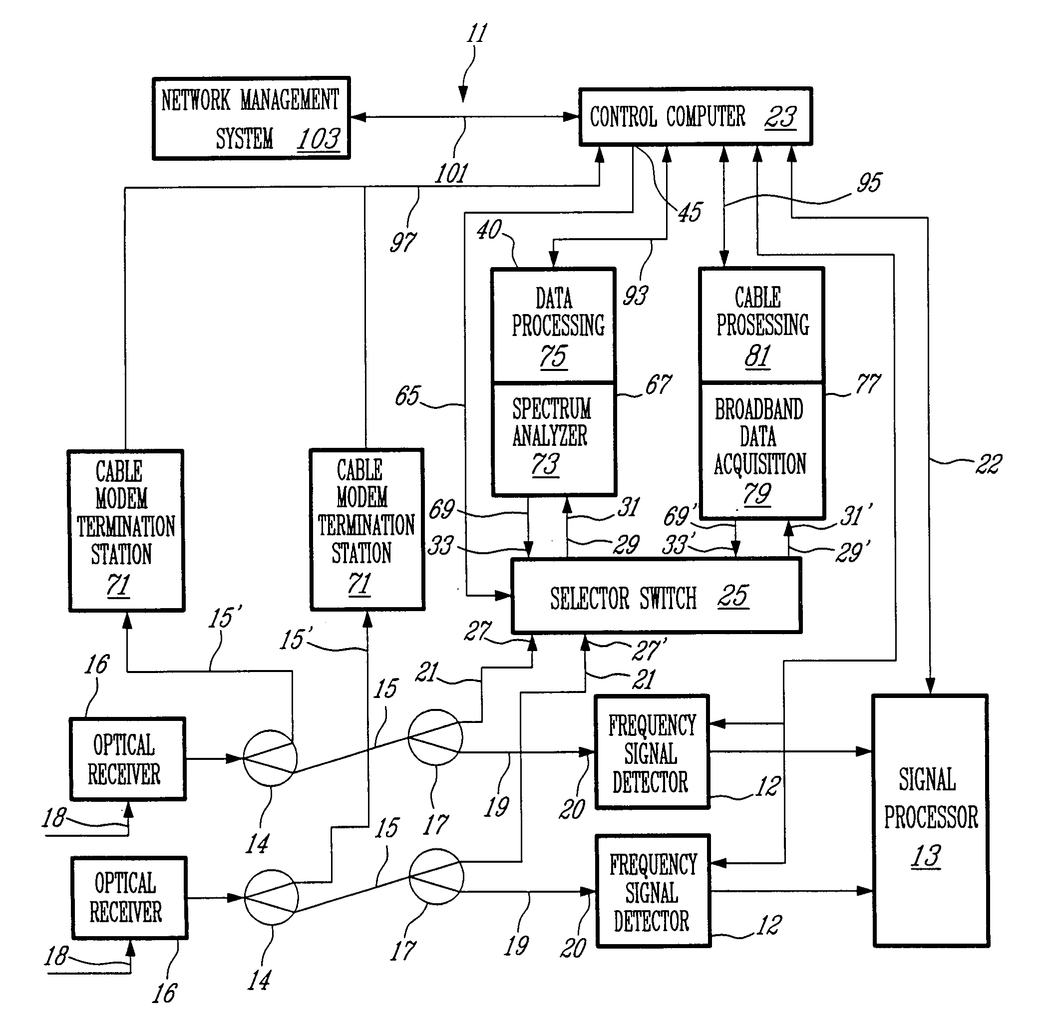
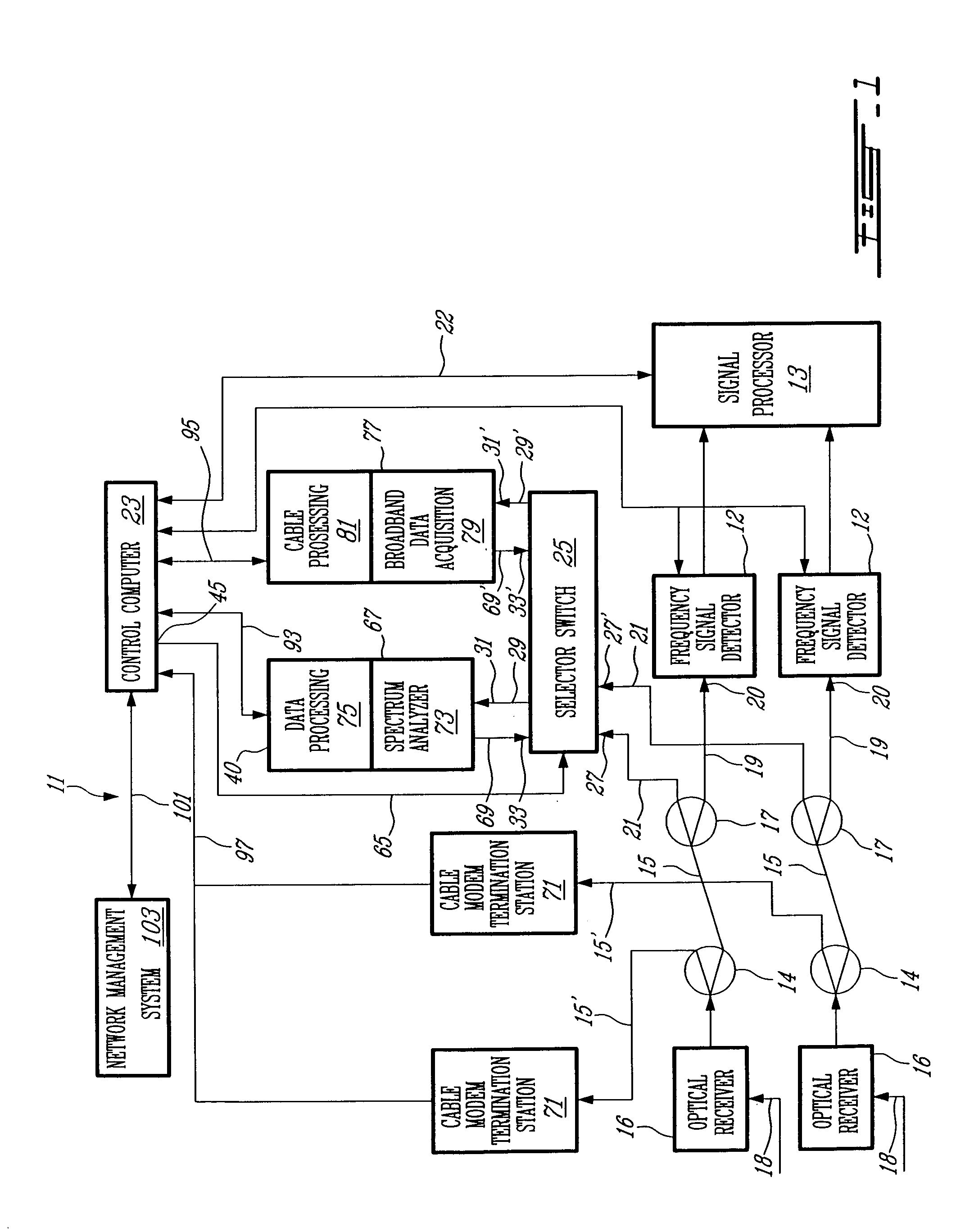
[0022]Referring now to FIG. 1, the monitoring system generally designated at 11 comprises a plurality of “glitch”, radio frequency signal detectors 12, each of which is coupled at input 20 thereof through series connected first splitter 14, reverse path line 15, second splitter 17 and reverse path line 19 to a respective one of a plurality of optical receivers 16 located at a headend or sub-headend of a CATV communication network of a HFC type, to receive from one of a multiplicity of nodes (not shown) through a respective fiber optic communication line 18, reverse path signals sent by subscribers connected to the node through drop lines made of coaxial cable. It is to be understood that the present invention may be advantageously used with communication networks adapted to the transmission of other types of data such as Internet data or telephony, as well as with other types of communication networks such as wholly fiber-based or coaxial-based networks. Where the fiber optic commun...


PUM


Abstract

A system for monitoring reverse paths of a bi-directional cable communication network such as a CATV network, to detect and analyze ingress signals entering a reverse path and ending at a network sub-headend or headend through a corresponding one of communication lines, comprises a plurality of radio frequency signal detectors connected thereto. The radio frequency signal detectors are provided with bandpass filter for receiving a radio frequency signal within the frequency band used, to generate corresponding output signals indicative of the strength of the received radio frequency signal. The output signal generated by the frequency signal detector which is coupled to the communication line corresponding to the ingress signal carrying path is indicative of the strength of the received ingress signal with received reverse signals. The system further comprises a signal processor for analyzing the detector output signals through comparison with one or more predetermined ingress thresholds to generate an alarm signal whenever the ingress signal is detected. The system further comprises a control computer receiving the alarm signal to generate monitoring sequence control data indicative of the communication line corresponding to the ingress signal carrying path to be monitored. The system also comprises a selector switch having a plurality of inputs being connected to the communication lines and being responsive to the monitoring sequence control data to select the input connected to the communication line to be monitored, and signal monitoring instrumentation such as a spectrum analyzer and a broadband analyzer coupled to an output of the switching device and being responsive to the monitoring sequence control data for analyzing the ingress signal and generating alarm message data accordingly. The control computer receives the alarm message data to further generate diagnostic sequence control data for the monitoring instrumentation also used to determine source characteristics of the ingress signal.

Description

FIELD OF THE INVENTION[0001]The present invention relates to the field of monitoring equipment for use with cable communication networks, and more particularly to systems and methods for monitoring reverse paths of bi-directional cable communication networks.BACKGROUND OF THE INVENTION[0002]Modern cable communication networks such as Community Antenna TeleVision (CATV) communication networks, are increasingly bi-directional, allowing subscribers to receive information in the forward direction (television signals, Internet data, telephony signals, etc.) but also to send information into the network in the reverse direction (Internet data, telephony signals, “Pay-per-view” ordering data, etc.). An almost universal structure of such network is the Hybrid Fiber Coaxial (HFC) where optical fiber links are used between the headend or sub-headends (hubs) and some distribution points or nodes where optical-to-electrical and the electrical-to-optical conversion is performed. Coaxial cables a...

Claims


Application Information

Patent Timeline
IPC IPC(8): H04N7/173H04B15/00H04B17/00H04N5/21H04N7/10H04N17/00
CPCH04N17/00
Inventor TERREAULT, GERARD
Owner AVANTRON TECH
Why Eureka
Try Eureka