Device forming fuel gas for fuel cell and composite material for hydrogen separation

a fuel cell and composite material technology, applied in catalyst activation/preparation, metal/metal-oxide/metal-hydroxide catalysts, bulk chemical production, etc., can solve the problems of other ill effects, slow hydrogen transmission speed, and thick film thickness

Inactive Publication Date: 2007-08-14
TOYOTA JIDOSHA KK
View PDF43 Cites 12 Cited by
  • Summary
  • Abstract
  • Description
  • Claims
  • Application Information

AI Technical Summary

Benefits of technology

[0011]The goal of the present invention is, for a device for generating fuel gas for fuel cells, to provide technology that makes the fuel gas generating device more compact.
[0012]To achieve this goal, with the present invention, first, a composite for hydrogen separation that has excellent hydrogen separation performance is used. Second, a structure that increases the hydrogen separation performance is used for the fuel gas generating device. With these inventions, it is possible to increase the hydrogen separation speed while avoiding ill effects such as pin holes, and to try to make the fuel gas generating device more compact. Of these inventions, the structure used for the fuel gas generating device does not have the hydrogen separation composite of the present invention as an absolute prerequisite, but if the hydrogen separation composite of the present inventions is used, it is obvious that there is the advantage of being able to make the fuel gas generating device more compact. Following, we will explain the hydrogen separation composite and its manufacturing method as well as the structure used for the fuel gas generating device in sequence for the present invention, and furthermore, we will explain a fuel cell system that uses this fuel gas generating device. Note that in the field of industrial use related to fuel cells, these inventions have a relationship for the common problems of increasing the hydrogen separation performance and making the device more compact.

Problems solved by technology

It is also possible to directly supply mixed gas to a fuel cell, but in addition to reactions at the electrode being hindered due to a drop in the hydrogen partial pressure at the electrode, there is also the risk of other ill effects such as having stable reactions being hindered due to toxification by carbon monoxide at the electrode, so normally, the mixed gas is supplied to the fuel cell after a process for reducing the carbon monoxide concentration or a process for separating only hydrogen is performed.
However, with hydrogen separation films of the prior art, there were problems in that the film thickness was thick and the hydrogen transmission speed was slow.
There were also problems of it being easy for pin holes to occur in the hydrogen separation film and mixed gas leaking on the purge side.
For example, with the technology noted in JAPANESE PATENT LAYING-OPEN GAZETTE 1-266833 described above, a hydrogen separation film is formed on the surface of a porous substrate, so the overall thickness of the hydrogen separation part unavoidably became larger.
Also, if an attempt was made to sufficiently prevent pin holes, the film thickness of the hydrogen separation film again became unavoidably thicker.
The hydrogen separation film noted in JAPANESE PATENT LAYING-OPEN GAZETTE 63-171617 has palladium supported into the pores of the porous film, but with a palladium thin film formed on the surface, part of this entered the pores, or fine particle palladium is supported in the inner walls of the pores, and it does not extend beyond this level, so the effect was not sufficient.
It is known that the transmission speed for the hydrogen separation film is proportional to the surface area of the separation film and inversely proportional to the film thickness, and when using a hydrogen separation film of the prior art, in addition to devices becoming larger due to the film thickness being thick, it becomes necessary to compensate for the thickness of the film using the surface area, so it was not possible to make the separation part sufficiently compact.
Also, to avoid gas leaks due to pin holes, the film thickness tends to become thicker, which is an obstacle to making the separation part more compact.
Moreover, when forming a fuel gas generating device without using a hydrogen separation film, it is necessary to have something like a part that reduces the concentration of carbon monoxide contained in the mixed gas, which causes the device to become even larger.

Method used


Image

  • Device forming fuel gas for fuel cell and composite material for hydrogen separation
  • Device forming fuel gas for fuel cell and composite material for hydrogen separation
  • Device forming fuel gas for fuel cell and composite material for hydrogen separation

Examples


second working example

G. Second Working Example

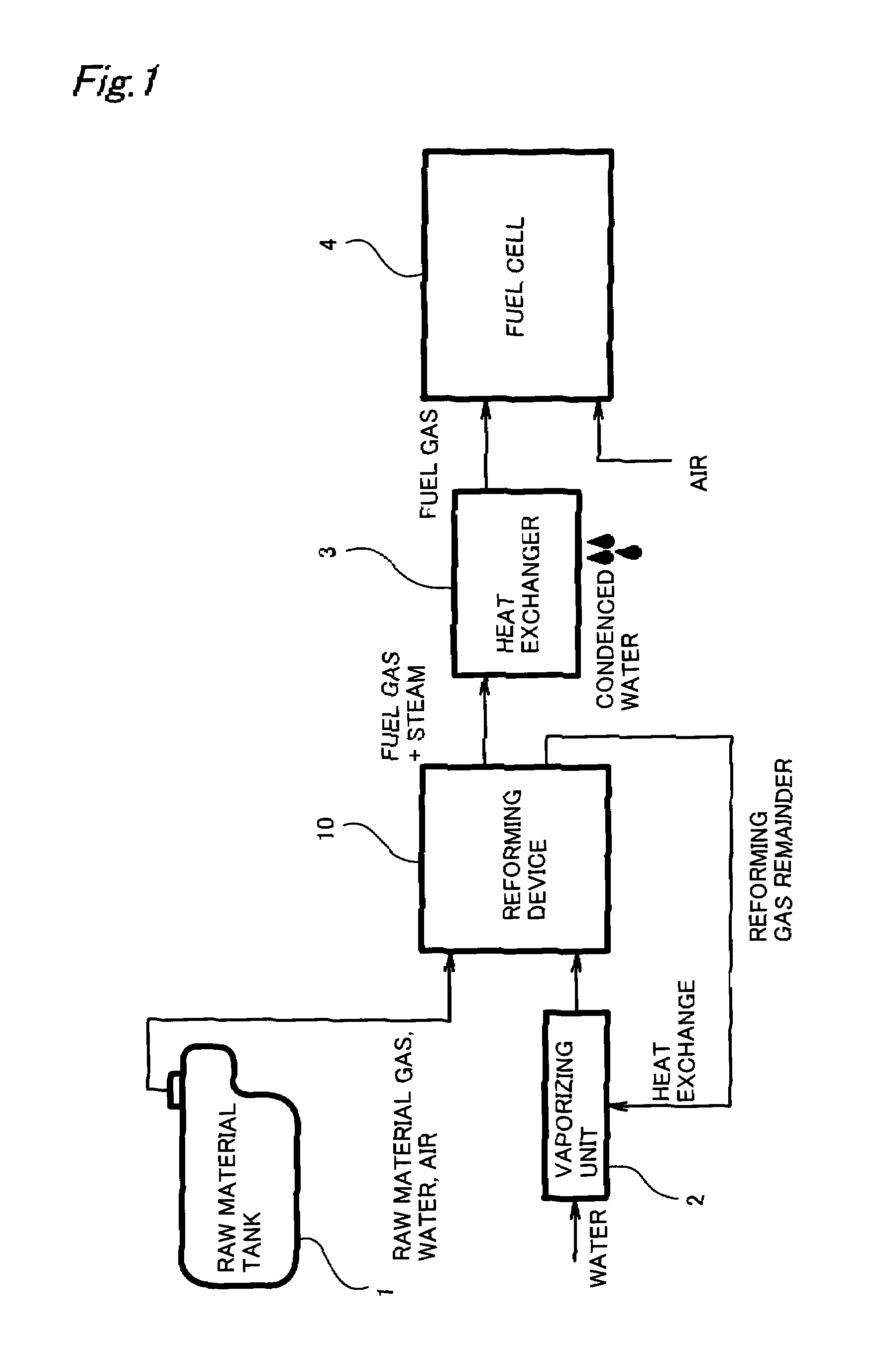
[0211]FIG. 17 is an explanatory diagram that shows the schematic structure of a fuel cell system as a second working example. With the first working example, we showed an example of using steam as the purge gas for fuel gas generating device 10. With the second working example, a raw material gas is used as the purge gas. Along with this, elements provided with the first working example such as vaporizer 2 for generating steam and heat exchanger 3 for condensing steam of the supplied gas to fuel cell 4 become unnecessary (see FIG. 1), so the overall system structure can be simplified.

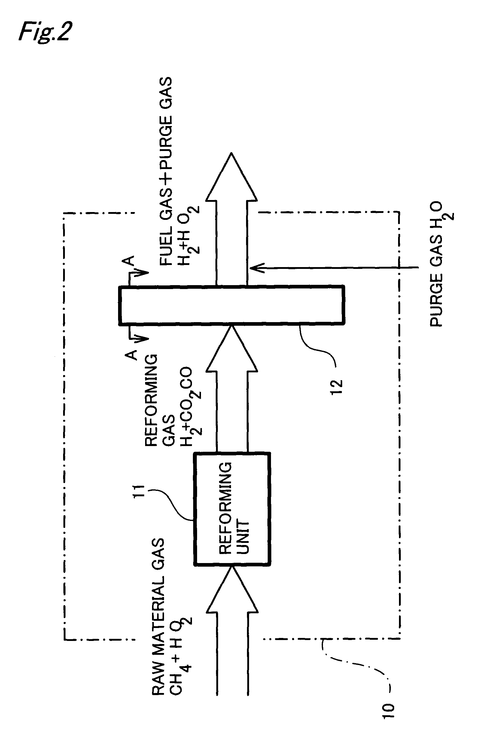
[0212]With the second working example, the structure of fuel gas generating device 10A is also different from the first working example. With the first working example, we showed an example where mixed gas was generated using chemical reaction unit 11, and only the hydrogen in this was extracted using hydrogen separation composite 12. Specifically, with the first working example...


PUM

PropertyMeasurementUnit
thicknessaaaaaaaaaa
operating temperatureaaaaaaaaaa
temperatureaaaaaaaaaa

Abstract

For a reforming device that generates fuel gas for fuel cells by decomposing hydrocarbon compounds such as natural gas and then using a hydrogen separation composite to selectively transmit hydrogen, a hydrogen separation composite having the following structure is used. A porous support medium made of ceramics, etc. is formed, and a hydrogen separation metal is supported in the pores so as to fill the inside of the support medium. It is also possible to support a reforming catalyst. By doing this, it is possible to increase the area at which the hydrogen separation metal contacts gas, so the hydrogen transmission performance is increased. Furthermore, to prevent raw material gas leaks due to pin holes, high pressure gas is supplied to the hydrogen extraction side, and the total pressure is made higher than the pressure on the raw material gas supply side without making the hydrogen partial pressure higher. By using these means, it is possible to increase the hydrogen separation performance for the reforming device and to make the device more compact.

Description

TECHNICAL FIELD[0001]The present invention relates to a fuel gas generating device that generates hydrogen-rich fuel gases supplied to fuel cells from a specified raw material that contains hydrogen atoms such as hydrocarbon, alcohol, ether, and aldehyde, and relates to composites for hydrogen separation used to separate hydrogen from gas generated by said fuel gas generating device.BACKGROUND ART[0002]What has been proposed is a fuel cell that generates electromotive force by comprising a hydrogen pole and oxygen pole that sandwich an electrolytic layer that transmits hydrogen ions and which causes a reaction expressed by the following reaction formulas with the hydrogen pole and oxygen pole, respectively.Hydrogen pole: H2→2H++2e−Oxygen pole: (1 / 2) O2+2H++2e−→H2O[0003]For a system that uses this kind of fuel cell as a power supply, hydrogen gas must be supplied on the hydrogen pole side. For supplying hydrogen gas, there is a method that directly uses reserve hydrogen gas using a h...

Claims


Application Information

Patent Timeline
Patent Type & Authority Patents(United States)
IPC IPC(8): C10L5/00B01D53/22B01D53/86B01D69/10B01D69/12B01D69/14B01D71/02B01J8/00B01J12/00B01J19/24B01J23/46B01J37/02B01J37/04C01B3/38C01B3/40C01B3/50C01B3/56H01M4/94H01M8/06H01M8/10H01M8/12H01M8/14
CPCB01D53/228B01D53/864B01D67/0069B01D67/0072B01D69/10B01D69/141B01D69/145B01D71/02B01D71/022B01J8/009B01J12/007B01J19/2425B01J19/2475B01J19/2485C01B3/38C01B3/40C01B3/503C01B3/505H01M4/94H01M8/0612H01M8/0662B01J2208/00849B01J2219/00137B01J2219/1944B01J2219/1945C01B2203/0233C01B2203/0283C01B2203/041C01B2203/044C01B2203/047C01B2203/0495C01B2203/066C01B2203/0883C01B2203/0894C01B2203/1011C01B2203/1023C01B2203/1052C01B2203/1058C01B2203/1064C01B2203/1076C01B2203/1082C01B2203/1223C01B2203/1241C01B2203/1276C01B2203/1288C01B2203/146C01B2203/80C01B2203/82Y02E60/50Y10S55/05B01D2325/06B01D2325/10Y02P20/52Y02P20/141Y02P70/50B01D71/0215B01D71/02231B01D69/108
Inventor SATO, HIROMICHIIGUCHI, SATOSHINAKATA, TOSHIHIDEAOYAMA, SATOSHI
Owner TOYOTA JIDOSHA KK
Why Eureka
Try Eureka