Metal/ceramic bonding substrate and method for producing same

a technology of metal/ceramic bonding and substrate, which is applied in the direction of metal layered products, solid-state devices, electrical devices, etc., can solve the problems of increasing the thickness of the portion of thermal conduction grease by one hundred micrometers, the heat sink characteristic of the substrate is extremely deteriorated, and it is not possible to obtain efficient heat conduction

Active Publication Date: 2007-08-14
DOWA METALTECH CO LTD
View PDF16 Cites 22 Cited by
  • Summary
  • Abstract
  • Description
  • Claims
  • Application Information

AI Technical Summary

Benefits of technology

[0011]It is therefore an object of the present invention to eliminate the aforementioned problems and to provide a metal/ceramic bonding substrate capable of preventing the reve...

Problems solved by technology

Therefore, if the base plate warps during soldering, clearance increases when the radiating fin or cooling jacket is mounted on the base plate, so that there is a problem in that the heat sink characteristic of the substrate extremely deteriorates.
Therefore, even if the base plate is caused to contact the radiating fin or cooling jacket, there are non-contact portions therebetween, so that it is not possible to obtain efficient heat conduction.
However, if only the base plate warps by one hundred micrometers, the thickness of that portion of the ...

Method used


Image

  • Metal/ceramic bonding substrate and method for producing same
  • Metal/ceramic bonding substrate and method for producing same
  • Metal/ceramic bonding substrate and method for producing same

Examples


example 1

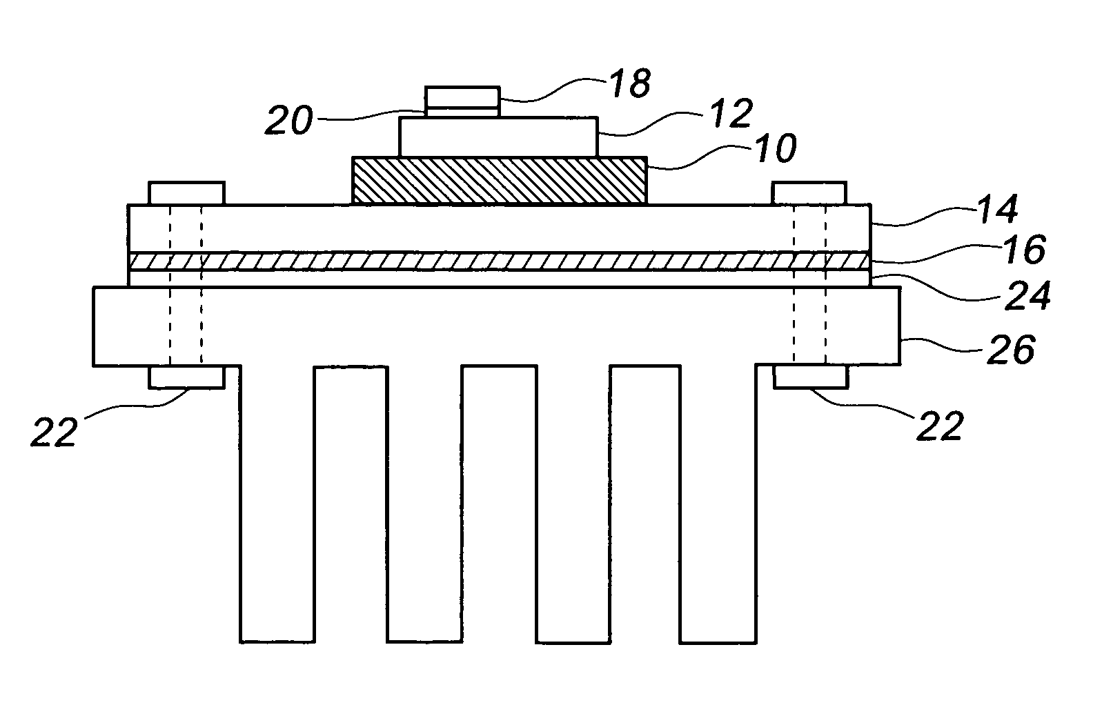
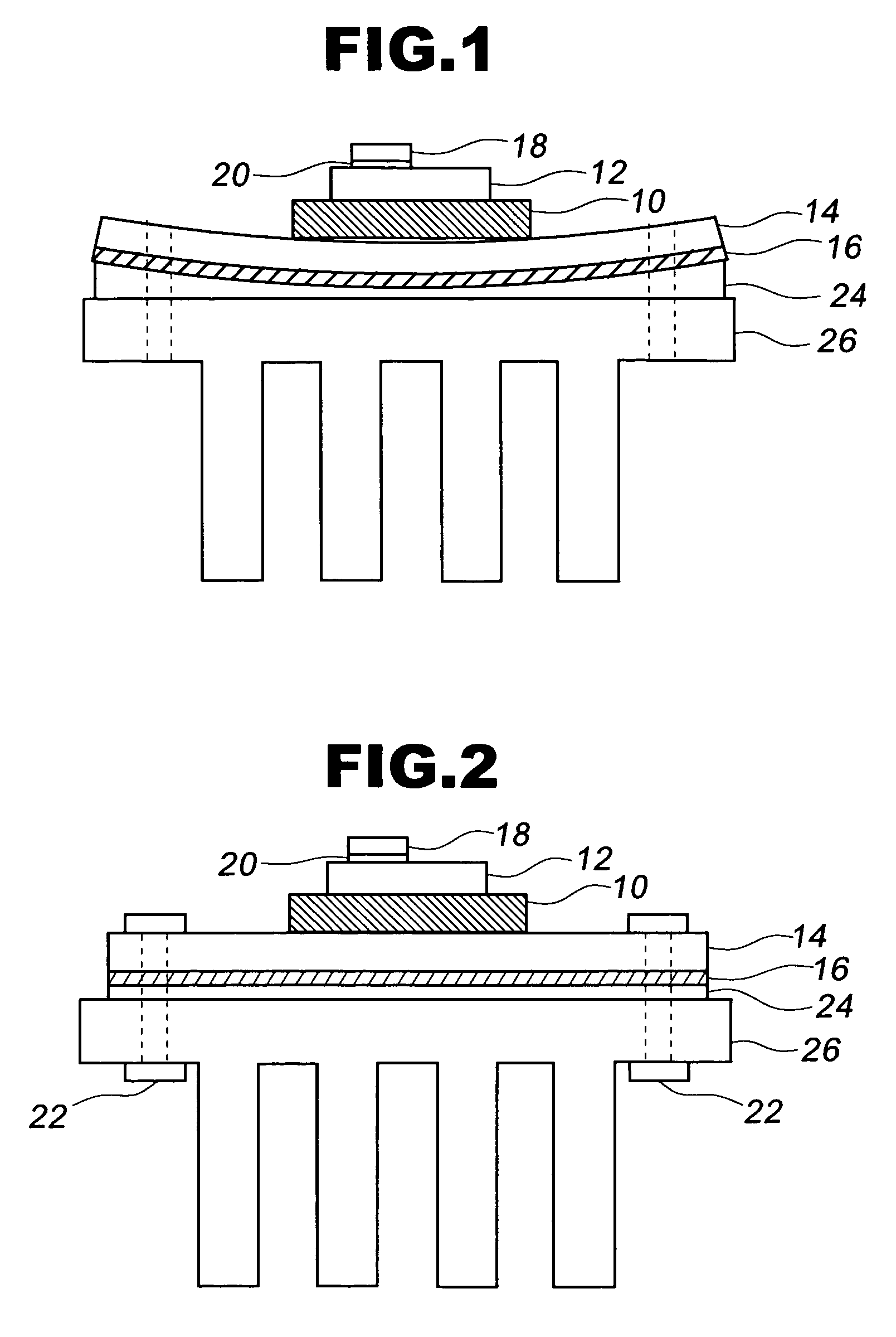
[0032]Two aluminum nitride substrates having a size of 90 mm×80 mm×0.635 mm were arranged in a carbon die at an interval of 10 mm, and molten pure aluminum having a purity of 99.9% (3N) was poured into the die in a furnace at 730° C. in an atmosphere of nitrogen gas while its coat was removed. The die has a groove having such a shape that a metal base plate having a size of 220 mm×90 mm×5 mm is formed on one side of each of the aluminum nitride substrates and that a metal circuit plate having a size of 89 mm×79 mm×0.4 mm is formed on the other side thereof. After the molten aluminum was poured into the die, the die was cooled to a room temperature to solidify aluminum to produce a bonding article having aluminum plates bonded to the ceramic substrates.

[0033]Then, a resist mask having a predetermined shape was printed on the metal circuit plate of the aluminum / ceramic bonding article to be dried to be etched with an iron chloride solution to form a circuit pattern. Moreover, ZrO2 sph...

examples 2 through 8

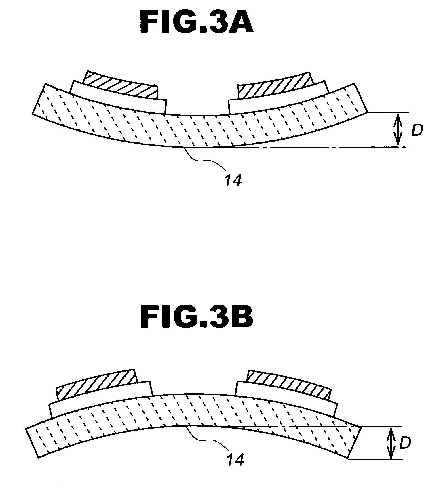
[0042]Aluminum / ceramic bonding articles were produced by the same method as that of Example 1, except that ZrO2 spherical balls having a size of 60 meshes or less were uniformly sprayed onto the metal base plate at a pressure of 4 kg / cm2 for five minutes (Example 2), at a pressure of 4 kg / cm2 for one minute (Example 3), at a pressure of 5 kg / cm2 for one minute (Example 4), at a pressure of 5 kg / cm2 for three minutes (Example 5), at a pressure of 5 kg / cm2 for five minutes (Example 6), at a pressure of 3 kg / cm2 for one minute (Example 7) and at a pressure of 3 kg / cm2 for three minutes (Example 8), respectively, to carry out the peening process. The warpages of the reverse of the metal base plates at an ordinary temperature were measured by the same method as that in Example 1. As a result, the measured warpages were +200 micrometers (Example 2), −50 micrometers (Example 3), +1000 micrometers (Example 4), +1500 micrometers (Example 5), +3000 micrometers (Example 6), −100 micrometers (E...


PUM

PropertyMeasurementUnit
Heightaaaaaaaaaa
Heightaaaaaaaaaa

Abstract

There is provided a metal/ceramic bonding substrate capable of preventing the reverse thereof from greatly warping so as to be concave even if it is heated for soldering. In the metal/ceramic bonding substrate, a metal circuit plate 12 is bonded to one side of a ceramic substrate 10, and a heat sink plate (metal base plate) 14 is bonded to the other side thereof. On the heat sink plate 14, a work-hardened layer 16 is formed by shot peening. On the metal circuit plate 12 of the metal/ceramic bonding substrate, semiconductor chips (Si chips) 18 are soldered (solder layer 20). Then, a power module is produced by a predetermined process. On the reverse (the side of the work-hardened layer 16) of the power module, a radiating fin 26 is mounted via a thermal grease 24 by means of screws 22 or the like.

Description

BACKGROUND OF THE INVENTION[0001]1. Field of the Invention[0002]The present invention generally relates to a metal / ceramic bonding substrate and a method for producing the same. More specifically, the invention relates to a metal / ceramic bonding substrate for use in super power electronic parts, such as power modules, a method for producing the same, and a power module using the metal / ceramic bonding substrate.[0003]2. Description of the Prior Art[0004]In recent years, power modules are used for controlling heavy-current for electric vehicles, electric railcars and machine tools. In conventional power modules, a ceramic insulating substrate is fixed by soldering to one side of a metal plate or compound material called base plate, and power ICs are fixed by soldering to the ceramic insulating substrate. On the other side (which will be hereinafter referred to as a “reverse”) of the base plate, a radiating fin or cooling jacket of a metal is mounted via a thermal conduction grease by ...

Claims


Application Information

Patent Timeline
IPC IPC(8): H05K1/00C04B37/00H01L23/12H01L23/13H01L23/373H05K1/02H05K1/03H05K3/00H05K3/20H05K3/22H05K7/20
CPCH01L23/13H01L23/3735H01L2924/09701H01L2924/3511H05K1/0271H05K1/0306Y10T428/12007H05K3/0058Y10T428/12493H01L2924/0002Y10T428/24926H01L2924/00
Inventor OSANAI, HIDEYOIBARAKI, SUSUMUIYODA, KENNAMIOKA, MAKOTO
Owner DOWA METALTECH CO LTD
Why Eureka
Try Eureka