Remotely powered and remotely interrogated wireless digital sensor telemetry system

a wireless digital sensor and telemetry system technology, applied in the field of sensors, can solve the problems of limited sensor data retrieval, common battery failure, and difficult sensor data retrieval

Active Publication Date: 2007-08-14
LORD CORP
View PDF10 Cites 1400 Cited by
  • Summary
  • Abstract
  • Description
  • Claims
  • Application Information

AI Technical Summary

Benefits of technology

[0013]It is an advantage of the present invention that timing is provided without a crystal.
[0014]It is an advantage of the present invention that the sensor transponder can be configured to provide data storage.
[0015]It is an advantage of the present invention that the sensor transponder can be configured to power a device using more power than is available from the reader.
[0016]It is an advantage of the present invention that the sensor transponder can be configured to provide bi-directional communication.

Problems solved by technology

Sensors on civil structures, such as buildings, dams, and bridges and orthopedic implants, such as artificial hips and knees, have been limited because of the need to provide power for sensor operation and interrogation.
Very small spaces where common batteries will not fit, extremely harsh environments where common batteries would fail, and metallic hermetically sealed enclosures that would interfere with electromagnetic communication are among the many environments where sensor data retrieval is difficult.
It has been undesirable to use batteries for power because of the possibility of leakage.
In addition, the implants must be as small as possible, limiting the size of batteries.
Providing power to such sensors has been particularly difficult.
The rotating shaft of a turbine engine poses another type of challenge since centrifugal forces exceeding 80,000 G's with very high ambient temperatures is routine.
Batteries cannot survive these forces and the high speed rotation precludes hardwiring or even slip-ring connections, which don't work reliably at such high RPM for extended periods of time.
Furthermore, crystals commonly used for system timing, have not been able to withstand these forces making placement and reading of sensors in such locations difficult.

Method used


Image

  • Remotely powered and remotely interrogated wireless digital sensor telemetry system
  • Remotely powered and remotely interrogated wireless digital sensor telemetry system
  • Remotely powered and remotely interrogated wireless digital sensor telemetry system

Examples


Embodiment Construction

[0050]The present invention substantially improves communication from switched reactance devices to enable powering a sensor transponder and communicate data from the sensor. Switched reactance circuits have advantage since they need no on-board power supply and receive all their power for operation from power transmitted to them by an external reader.

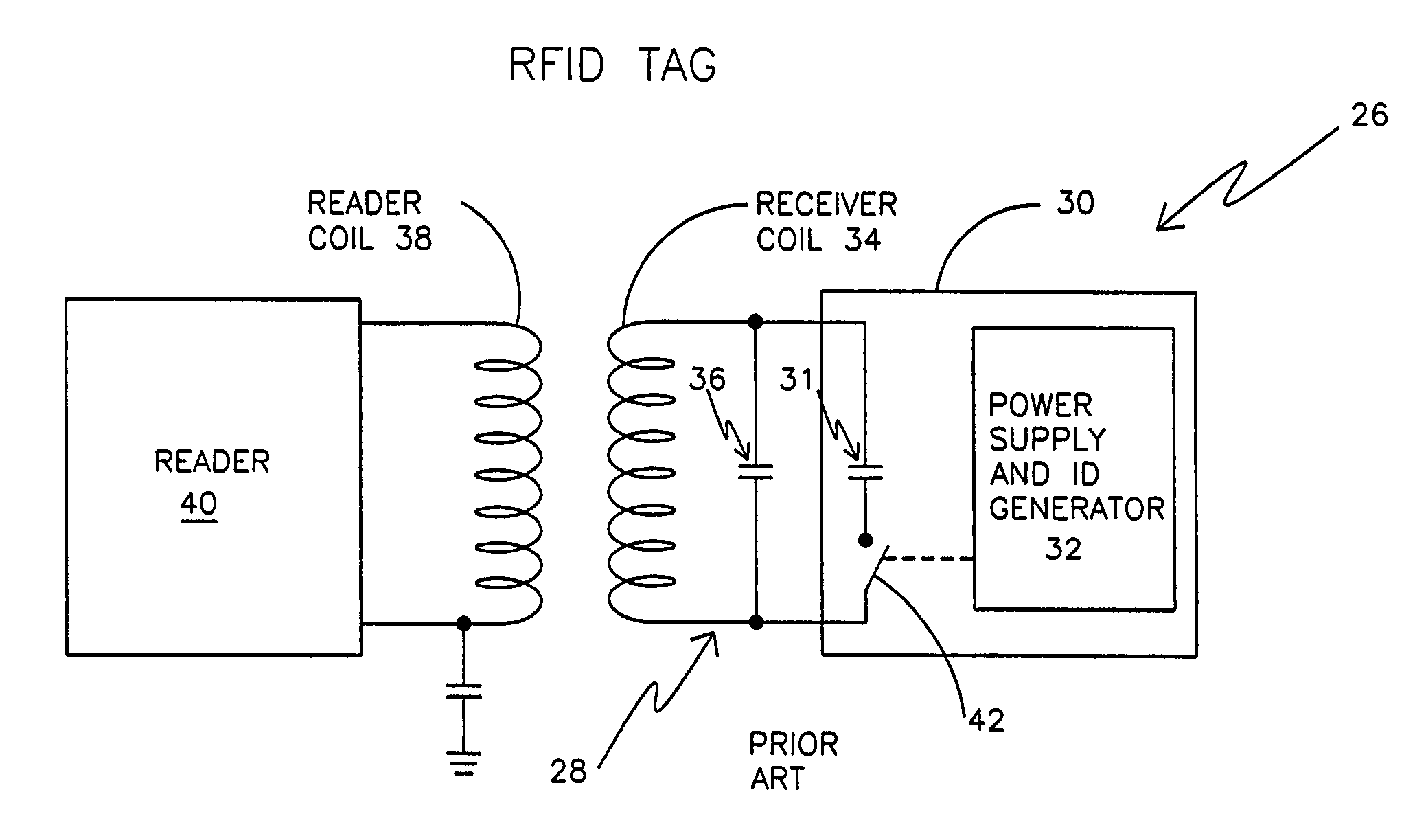
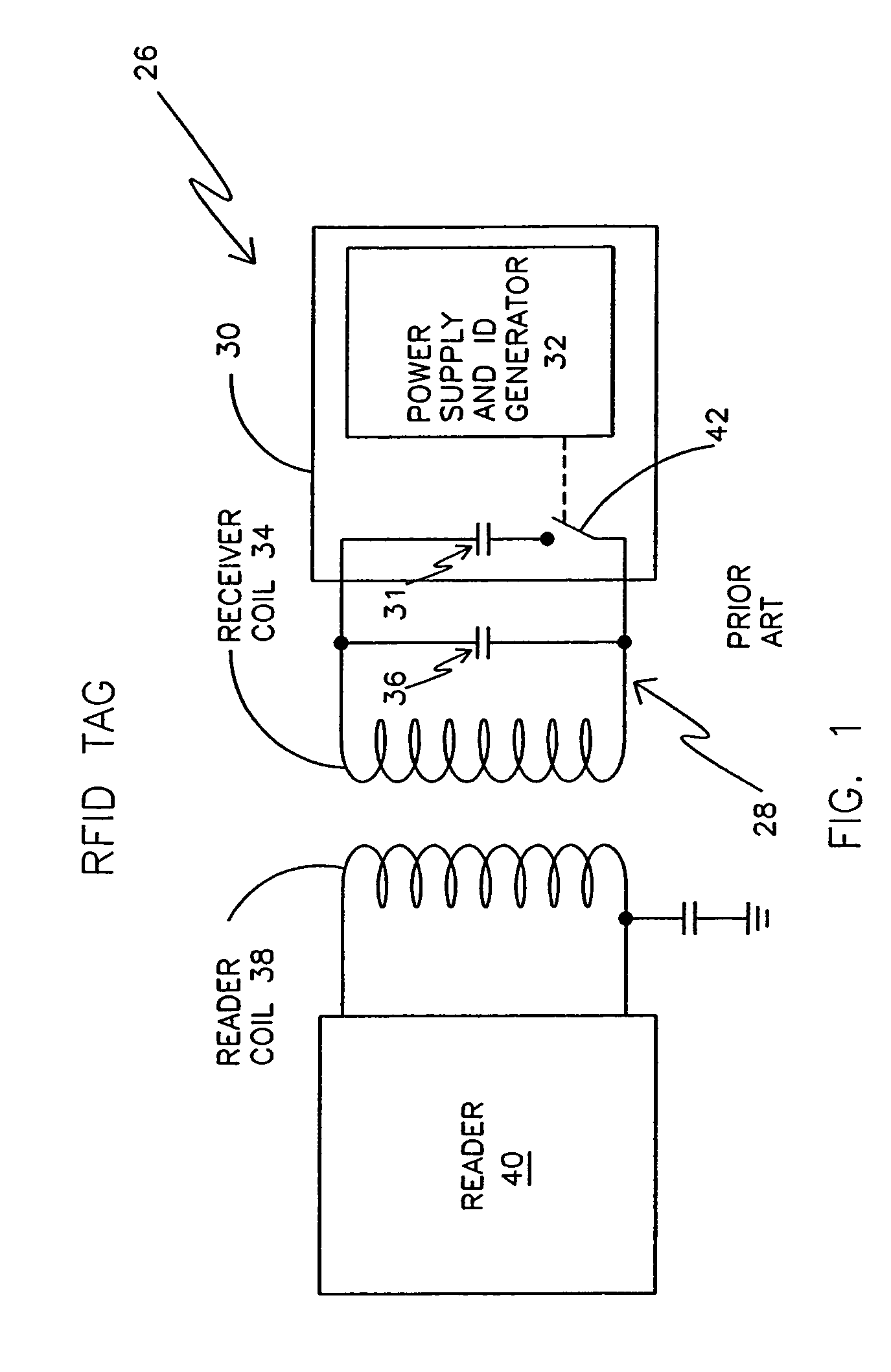
[0051]Remote electromagnetic powering with switched reactance communications has been used to power up and read identification codes on Radio Frequency IDentification (RFID) tags. RFID tag 26 has tank circuit 28 with its switched reactance circuit 30. Capacitor 31 of switched reactance circuit 30 is brought into or out of tank circuit 28 under the control of power supply and ID generator 32, as shown in FIG. 1. Switched reactance circuit 30 is powered through on board receiver coil 34 which, along with capacitor 36 makes up tank circuit 28. Receiver coil 34 can be a coil, as shown or it can be an antenna. In this application the phrase...


PUM


Abstract

An electronic system includes a reader and a remotely powered and remotely interrogated sensor transponder. The sensor transponder includes a coil or an antenna, a switched reactance circuit, a processor, and a sensor. The sensor transponder receives power radiated from the reader to the coil or antenna. The sensor uses the power for sensing. The sensor transponder is capable of processing sensor data in the processor and transmitting the sensor data to the reader using the switched reactance circuit. In one embodiment, the receiver coil or antenna is part of a resonant tank circuit which includes an impedance matching circuit. The impedance matching circuit is connected to the receiver coil or antenna to provide greater current to the sensor or other power-using device than would be available to the sensor or other power-using device if the sensor or other power-using device were connected between the first and second end. The impedance matching circuit can be two or more taps to the coil or antenna.

Description

RELATED APPLICATIONS[0001]This patent application is related to U.S. patent applications Ser. No. 09 / 731,066 09 / 801,230 and now U.S. Pat. No. 6,622,567, 09 / 768,858 and now U.S. Pat. No. 6,433,629, 10 / 215,752 which is a divisional of the U.S. Pat. No. 6,433,629, 09 / 114,106 and now U.S. Pat. No. 6,529,127, and U.S. patent application 10 / 379,224, which was a continuation of U.S. Provisional Patent Application 60 / 362,432, all of which are incorporated herein by reference.[0002]This patent application claims priority of Provisional Patent Applications 60 / 412,725 filed on Sep. 23, 2002 and 60 / 419,994 filed on Oct. 21, 2002, both of which are entitled “Remotely Powered, Remotely Interrogated wireless Digital Sensor Telemetry System,” and both of which are incorporated herein by reference. This application is a continuation-in-part of those Provisional Patent Applications.FIELD OF THE INVENTION[0003]This invention generally relates to sensors. More particularly, it relates to a circuit for ...

Claims


Application Information

Patent Timeline
Patent Type & Authority Patents(United States)
IPC IPC(8): G08B13/14A61B19/00A61F2/02A61F2/36A61F2/38A61F2/44A61F2/46A61F2/48A61N1/08G06K19/07
CPCA61F2/4657A61N1/08G06K7/10316G06K7/10336G06K19/0701G06K19/0723A61B19/46A61F2/36A61F2/3676A61F2/38A61F2/3859A61F2/389A61F2/44A61F2002/3067A61F2002/4658A61F2002/4666A61F2002/488A61F2250/0002A61B90/06A61F2/488
Inventor HAMEL, MICHAEL JOHNARMS, STEVEN W.TOWNSEND, CHRISTOPHER P.
Owner LORD CORP
Why Eureka
Try Eureka