
Video game play using panoramically-composited depth-mapped cube mapping

a cube mapping and video game technology, applied in the field of video game play, can solve the problems of inability to render the game in the time available, the most advanced home video game system lacks the processing resources of video game designers, and the complexity of detailed images is exceedingly high on the processors and other internal circuitry of relatively inexpensive video game system processors

Active Publication Date: 2007-08-14
NINTENDO CO LTD
View PDF26 Cites 36 Cited by
  • Summary
  • Abstract
  • Description
  • Claims
  • Application Information

AI Technical Summary

Benefits of technology

[0003]Modern home video games are more exciting and realistic than ever before. Relatively inexpensive 3D home video game platforms contain as much processing power as advanced computer graphics workstations of yesteryear. They can dynamically, interactively produce rich, realistic interesting displays of characters and other objects moving about in and interacting with a simulated three-dimensional world. From your living room on a home color television set, you can now fly virtual fighter planes and spacecraft through simulated battles, drive virtual race cars over simulated race tracks, ride virtual snowboards over simulated snow fields and ski slopes, race simulated jet skis over simulated water surfaces, and journey through exciting virtual worlds encountering all sorts of virtual characters and situations—just to name a few examples—all with highly realistic and exciting 3D images.
[0005]One approach to help solve this problem involves pre-rendering complicated scenes in advance and then adapting or otherwise manipulating those scenes in real-time to provide interactive video game play. For example, it is possible for a video game designer at the time he or she creates a video game to use a very powerful computer to pre-calculate and pre-render background scenery and other images. Developing a new video game can sometimes take a year or more, so using a high-power computer graphics workstation or even a supercomputer for hours at a time to render individual complicated background images is feasible. Such interesting and complicated background images are then often essentially “pasted” onto 3D surfaces through use of texture mapping during real-time video game play. This technique can be used to provide rich and interesting background and other video game play elements without a corresponding substantial increase in real-time processing overhead.
[0006]While such pre-rendered texture maps have been used with substantial advantageous results in the past, they have some shortcomings in interactive video game play. For example, texture-mapping a pre-rendered image onto a 3D surface during interactive video game play can successfully create impressive visual complexity but may let down the user who wants his or her video game character or other moving object to interact with that complexity. The tremendous advantageous 3D video games have over 2D video games is the ability of moving objects to interact in three dimensions with other elements in the scene. Pre-rendered textures, in contrast, are essentially 2D images that are warped or wrapped onto 3D surfaces but still remain two-dimensional. One analogy that is apt for at least some applications is to think of a texture as being like a complex photograph pasted onto a billboard. From a distance, the photograph can look extremely realistic. However, if you walk up and touch the billboard you will immediately find out that the image is only two dimensional and cannot be interacted with in three dimensions.
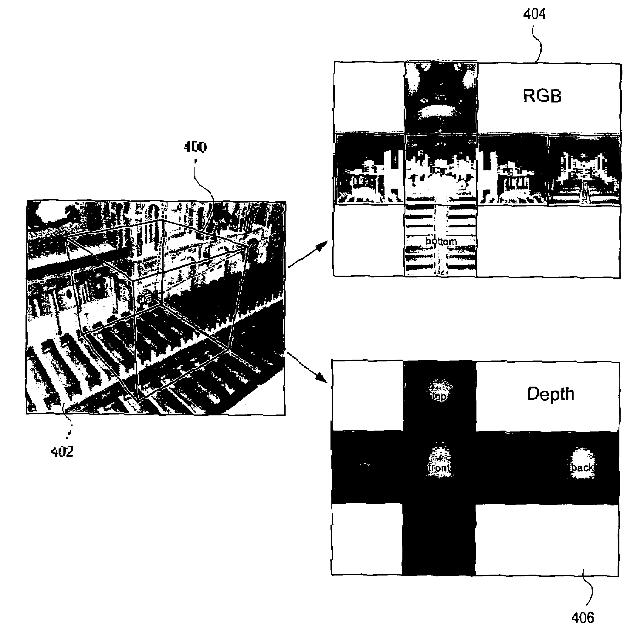
[0008]In one embodiment, we use a known technique called cube mapping to pre-render images defining a 3D scene. Cube mapping is a form of environment mapping that has been used in the past to provide realistic reflection mapping independent of viewpoint. For example, one common usage of environment mapping is to add realistic reflections to a 3D-rendered scene. Imagine a mirror hanging on the wall. The mirror reflects the scene in the room. As the viewer moves about the room, his or her viewpoint changes so that different objects in the room become visible in the mirror. Cube mapping has been used in the past or provide these and other reflection effects.
[0009]We use cube mapping for a somewhat different purpose—to pre-render a three-dimensional scene or universe such as for example a landscape, the interior of a great cathedral, a castle, or any other desired realistic or fantastic scene. We then add depth to the pre-rendered scene by creating and supplying a depth buffer for each cube-mapped image. The depth buffer defines depths of different objects depicted in the cube map. Using the depth buffer in combination with the cube map allows moving objects to interact with the cube-mapped image in complex, three-dimensional ways. For example, depending upon the effect desired, moving objects can obstruct or be obstructed by some but not other elements depicted in the cube map and / or collide with such elements. The resulting depth information supplied to a panoramically-composited cube map provides a complex interactive visual scene with a degree of 3D realism and interactivity not previously available in conventional strictly 2D texture mapped games.

Problems solved by technology

While home video game systems are now relatively powerful, even the most advanced home video game system lacks the processing resources that video game designers dream about.
More complicated and detailed images place exceedingly high demands on relatively inexpensive video game system processors and other internal circuitry.
If the image is too complicated, the video game platform will not be able to render it in the time available.
This can sometimes result in incomplete, only partially rendered images that may appear flawed and unrealistic and thus disappoint users.
For example, texture-mapping a pre-rendered image onto a 3D surface during interactive video game play can successfully create impressive visual complexity but may let down the user who wants his or her video game character or other moving object to interact with that complexity.
However, if you walk up and touch the billboard you will immediately find out that the image is only two dimensional and cannot be interacted with in three dimensions.
For example, depending upon the effect desired, moving objects can obstruct or be obstructed by some but not other elements depicted in the cube map and / or collide with such elements.

Method used


Image

  • Video game play using panoramically-composited depth-mapped cube mapping
  • Video game play using panoramically-composited depth-mapped cube mapping
  • Video game play using panoramically-composited depth-mapped cube mapping

Examples


example images

[0056]FIGS. 7A-7G show example images that are possible in the cathedral interior scene of FIG. 4A when an exemplary moving object 500 interacts with the cube-mapped scene. The moving object 500 shown in FIGS. 7A-7G is a cube for purposes of illustration only—any animated or non-animated object of any configuration could be used instead. FIG. 7A shows moving object 500 obstructing and being obstructed by different portions of the cube-mapped virtual 3D environment—in this case a railing 502 on the clere story of the virtual cathedral. FIG. 7B shows the same moving object 500 obstructing and being obstructed by a column 504 and also descending and thus being obstructed by portions of the tile floor surface 506 of the virtual cathedral. FIG. 7C shows the same cubic moving object 500 obstructing and being obstructed by ceiling details such as shown in FIG. 5D. FIG. 7D shows the moving object 500 obstructing and being obstructed by an archway detail 508. FIG. 7E shows moving object 500 ...

example enhancements

to Panoramic Compositing

[0058]Example Enhanced Antialiasing:

[0059]The quality of composited renderings could be improved with better antialiasing. This can be achieved by allowing multiple Z values and multiple color values for edge pixels of foreground objects.

[0060]We would get a lot of benefit even with just two Z values per pixel. This allows a high quality solution to the halo artifacts which occur when real-time CG characters are positioned between background and foreground pre-rendered elements in 1-depth-sample per pixel compositing.

[0061]The following algorithm can be used to render anti-aliased edges in the two depth samples per pixel case.

[0062]1. Render the furthest depth value and RGB value first.

[0063]2. Composite the real-time character as usual.

[0064]3. Alpha-blend on the foreground edges—alpha comes from foreground coverage value.

[0065]Note that foreground edges occupy only a small percentage of the pixels, so the antialiasing pass does not need to consume a full fr...


PUM


Abstract

Video game play rendered using a panoramic view of a cube map style rendering uses an associated depth map to supply three-dimensionality to the pre-rendered scene. The resulting panoramic rendering may be indistinguishable from rendering the original scene in real-time except that the background is of pre-rendered quality.

Description

CROSS-REFERENCES TO RELATED APPLICATIONS[0001]Priority is claimed from application No. 60 / 468,645 filed May 8, 2003, which is incorporated herein by reference.FIELD[0002]The technology herein relates to video game play, and more particularly to efficient 3D video game rendering techniques using pre-rendered cube or other environment maps.BACKGROUND AND SUMMARY[0003]Modern home video games are more exciting and realistic than ever before. Relatively inexpensive 3D home video game platforms contain as much processing power as advanced computer graphics workstations of yesteryear. They can dynamically, interactively produce rich, realistic interesting displays of characters and other objects moving about in and interacting with a simulated three-dimensional world. From your living room on a home color television set, you can now fly virtual fighter planes and spacecraft through simulated battles, drive virtual race cars over simulated race tracks, ride virtual snowboards over simulated...

Claims


Application Information

Patent Timeline
Patent Type & Authority Patents(United States)
IPC IPC(8): G06T15/40A63F13/10G06T15/04
CPCA63F13/10G06T15/04G06T15/405A63F2300/66A63F13/45A63F13/52
Inventor DONNELLY, PAUL
Owner NINTENDO CO LTD
Learn More