Method, apparatus, and system for using a synchronous burst time plan in a communication network

a communication network and synchronous technology, applied in the field of satellite communication networks, can solve the problems of channel subject to further attenuation, extremely long one-way delay, cost of radio-frequency (rf), etc., and achieve the effect of reducing the effective data rate of the link, wasting bandwidth, and reacting quickly

Active Publication Date: 2007-08-14
ST ENG IDIRECT INC
View PDF24 Cites 31 Cited by
  • Summary
  • Abstract
  • Description
  • Claims
  • Application Information

AI Technical Summary

Benefits of technology

[0020]The present invention provides a method to enable a satellite network system to dynamically monitor and adapt in real time to changing conditions on each satellite channel and changing traffic patterns at the user nodes. Another object of this invention is to maximize the quality of service that all users of the network experience by ensuring that each user node is communicating with the hub station at a higher data rate than conventionally possible while staying above a threshold bit error rate, and furthermore, to ensure that the TDMA upstream channel is shared amongst all users and applications according to predefined rules.
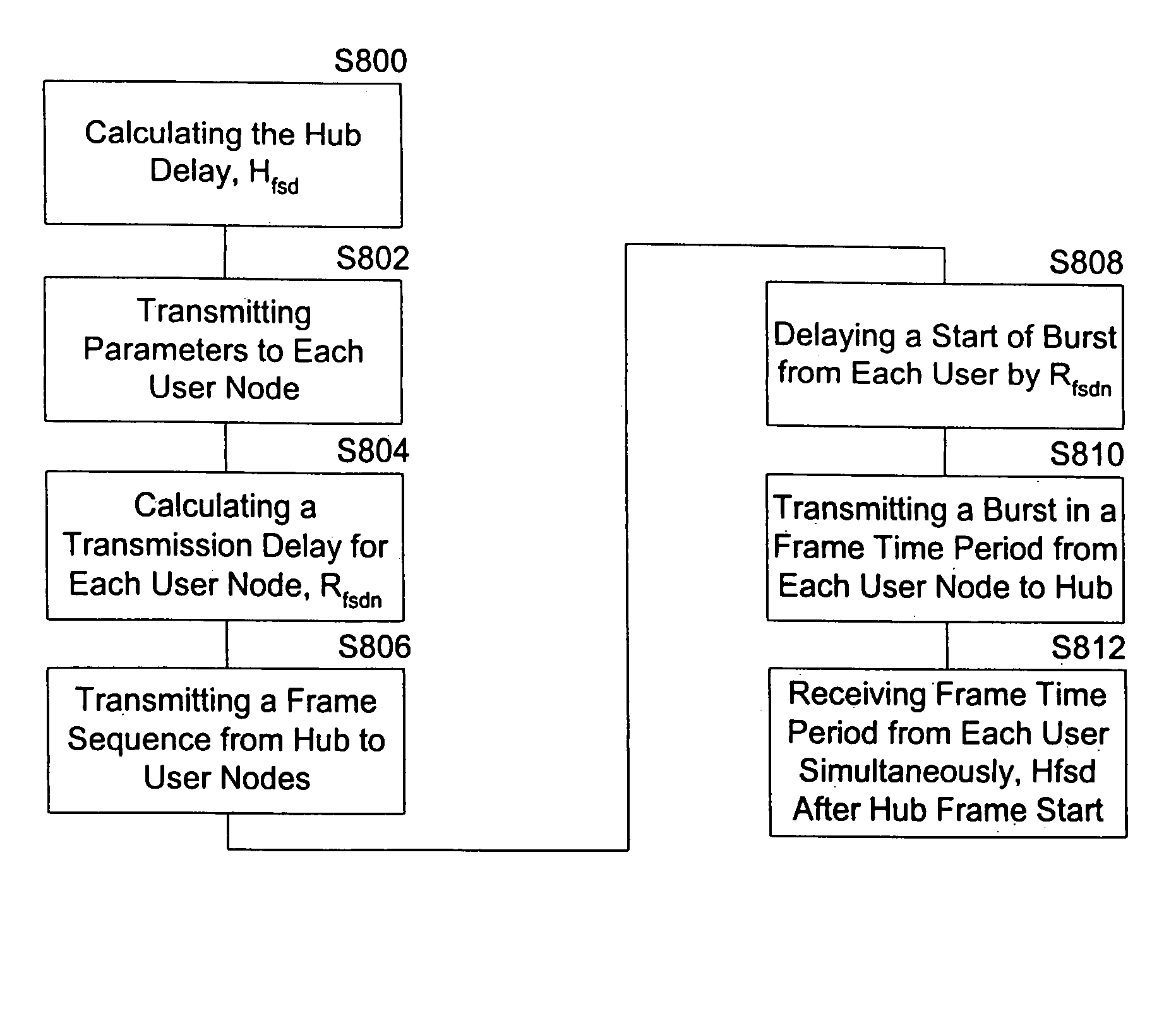
[0022]To enable the DA and UC processes to work reliably and react quickly to changing channel conditions, a synchronous Burst Time Plan (sBTP) is employed. The sBTP ensures that the propagation delay is a same integer number of frames for all node-to-hub paths. This enables time slots, modulation, and FEC to be changed every frame even though that frame is much shorter than the propagation delay between the hub and the user nodes.
[0023]Since rain fade is a physical property of the satellite channel, it is not possible to directly counteract its effect without making a tradeoff. The traditional tradeoffs include either over-designing the link (which requires using more expensive RF equipment and possibly wasting bandwidth by power limiting the link), or allowing the BER to increase (which could become so bad that it causes a complete outage). The UC and DR processes take a different approach, which is to lower the effective data rate of the link by changing modulation or FEC during the rain fade without BER degradation. Using traditional methods, the link is designed for some availability based on the percentage of time during the year that there is heavy rain at the user node location. For example, if it is expected that there will be rain fade of greater than 3 dB 0.01% of the year, the link can be over-designed by 3 dB to produce a link that is 99.99% available. If the same link were designed using a UC and DR process, the link could be designed with no rain margin. When a rain fade occurs, UC and DR sense the condition and change to an alternate modulation and FEC code which requires 3 dB less SNR in order to maintain the desired BER. The consequence of using the alternate modulation and FEC is that the data rate of the link is reduced (e.g., switching from QPSK to BPSK halves the number of bits per second, and increasing the FEC rate could reduce the data rate further). However, as recognized by the present inventors it is preferable to avoid the cost of over-designing the link in exchange for operating at a lower data rate during the infrequent periods of heavy rain. In fact, the UC and DR capability results in users getting higher performance than they would using a traditional link design by choosing not to decrease the cost of RF equipment, but instead to use the rain margin that is no longer required to increase the bit rate that they can operate under clear sky conditions. Either way, UC and DR allow the users a valuable choice that they would not otherwise have.

Problems solved by technology

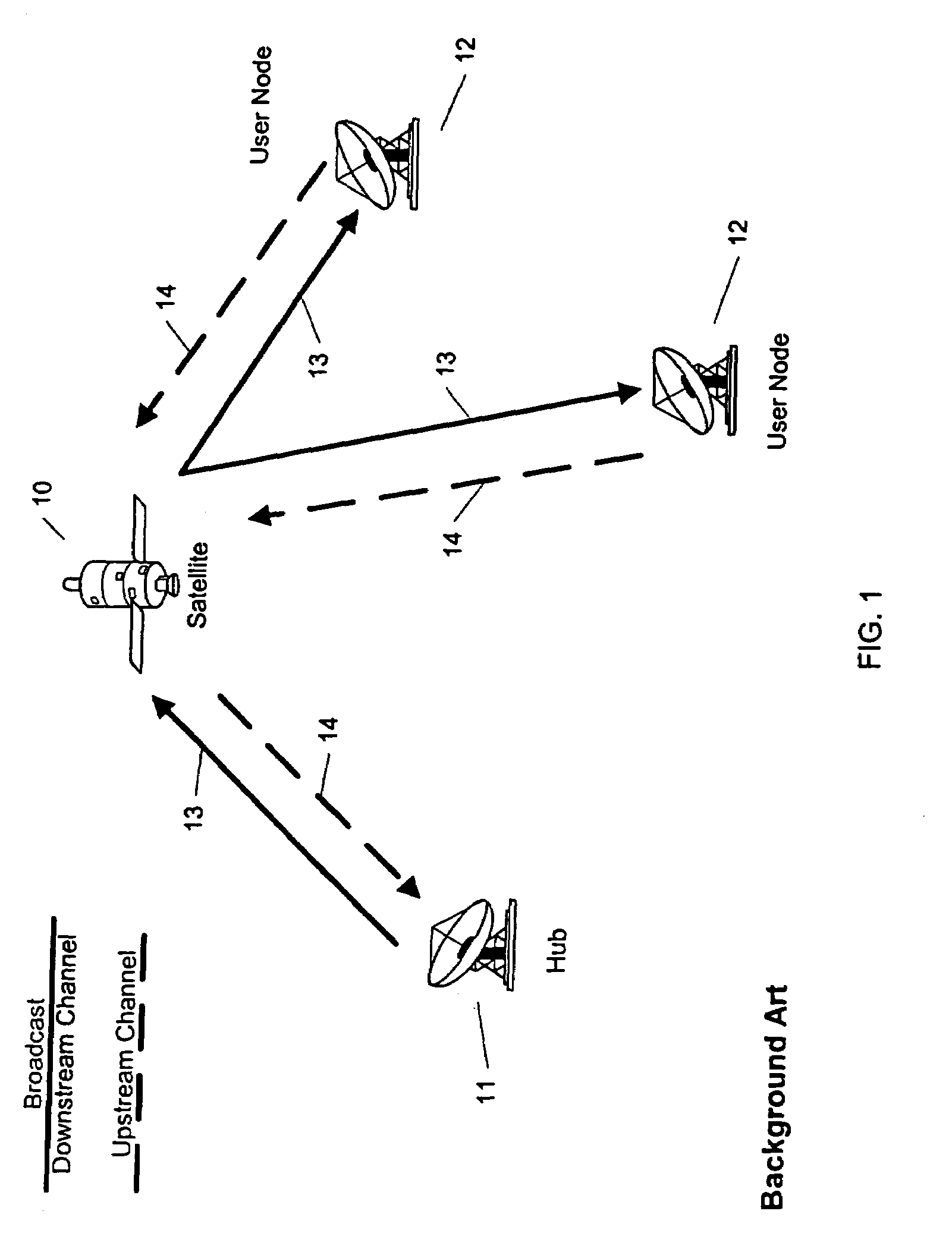
The geo-stationary satellite channel is well known to have an extremely long one-way delay (up to ˜300 ms) and it is extremely power limited due to the long propagation delay which results in the need to operate at the lowest signal-to-noise-ratio (SNR) possible in order to minimize the cost of radio-frequency (RF) equipment.
Additionally, the channel is subject to further attenuation due to atmospheric conditions, some of which are variable, such as rain fade.
If the SNR becomes too low, the bit error rate increases to an unacceptable level and all communication breaks down and creates adverse effects up the entire protocol stack.
In particular, the Layer 2 slot allocation process breaks down very quickly for reliable protocol-protected data since the bandwidth demanded by user nodes is allocated by the system, but the user nodes' demand level is not reduced since data is lost and must be retransmitted.
The situation worsens when the SNR is reduced so badly due to a fade condition that even station-keeping control information cannot get through and the user node actually drops out of the network.
In this case the slot allocation process may waste valuable bandwidth before learning of the outage by allocating slots to the user node that the user node is unable to use.
Problems continue to arise as modern higher-level protocols are considered such as Voice over IP (VoIP) and streaming media which are sensitive to packet jitter.
These protocols are designed to overcome the jitter of Internet Protocol (IP) traveling over terrestrial connections where the jitter is primarily due to queuing delays; however, the jitter introduced by a shared TDMA upstream satellite channel is often enough to degrade performance even when quality of the Layer 1 connection is excellent.
Any Layer 2 control protocol designed to maximize throughput and mitigate the performance problems experienced by users of satellite networks is itself subject to the same problems as the application data packets.
Traditional control methods requiring handshaking are not very helpful since it takes too long, for example, to command one user node to stop transmitting on a TDMA slot, wait for an acknowledgement, and then command another user node to begin.
Adding multiple upstream channels such that user nodes may transmit on any one of several channels helps matters somewhat since it increases the possible number of transmission opportunities per frame, however it does not solve the problem of the delay incurred while changes are made to the slot allocation.
An additional Layer 1 problem in traditional satellite networks, as recognized by the present inventors, is that the network's link budgets are over-designed due to the lack of adaptability of the modulation, demodulation, and FEC processes used therein.
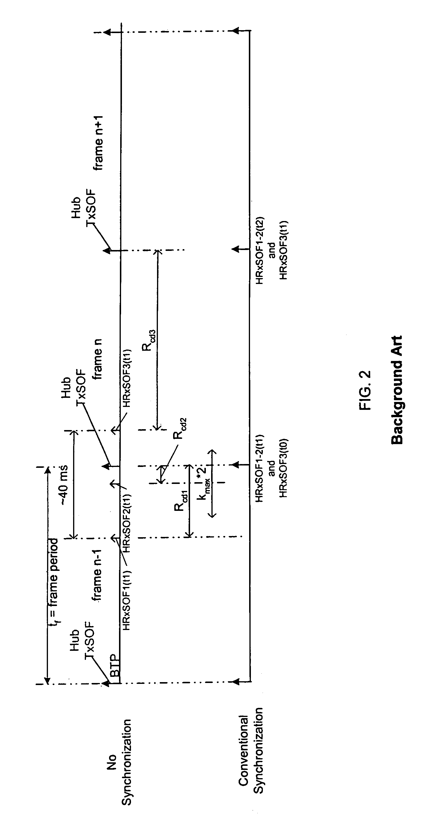
The conventional approach synchronizes HRxSOFn of each user node, but arrival time variation resulting from satellite tracking error disadvantageously results in some HRxSOFn occurring during hub frame n and some HRxSOFn occurring during hub frame n−1.
Thus, data bursts arriving at the Hub cannot be assumed to have all been sent during the same frame time, thereby complicating network control methods and increasing response time to control commands sent from the Hub.

Method used


Image

  • Method, apparatus, and system for using a synchronous burst time plan in a communication network
  • Method, apparatus, and system for using a synchronous burst time plan in a communication network
  • Method, apparatus, and system for using a synchronous burst time plan in a communication network

Examples


example real

Time Demand Information (for Current Frame Time)

[0113]

NODETotal Demand% Real TimeCIRA0 slots0NoB80 slots0NoC40 slots25%NoD10 slots0YesE0 slots0NoF5 slots0NoG60 slots0YesH40 slots50%No

Example Demand Assignment Decision Process Explanation[0114]Two upstream carriers with 100 slots per frame each results in 200 slots available for the current frame.[0115]235 slots requested so DA will have to make a decision.[0116]Per the Example Prioritization Rules, the Minimum Data Rate is satisfied first for all nodes regardless of their current demand. Since a single slot represents 1 kbit of data, a minimum rate rule of 10 kbps is satisfied by allocating at least one slot per frame.[0117]one slot contains 1000 data bits.

Example Slot Allocation after Satisfying the Minimum Data Rate Constraint:

[0118]

NODESlotsA1 slotB2 slotsC1 slotD5 slotsE1 slotF2 slotsG1 slotH5 slots

A total of 18 slots have been allocated in this example and 182 slots remain free.[0119]Per the prioritization rules, CIR is satisfi...


PUM


Abstract

A communication network control method for a communication network including a hub and a plurality of user nodes includes adjusting system parameters to maximize communication data rate and minimize bit error rate given current conditions of the wireless channel, current loading of the network, and user constraints. In particular, the method includes transmitting a first and second frame with first and second control information from the hub to each user node, and transmitting a first and second respective data burst from each of the user nodes to the hub according to the first and second control information. The first data burst from each user node arrives simultaneously at the hub, and the second data burst from each user node arrives simultaneously at the hub. Further, the second data burst from each user node arrives immediately following the arrival of the first data burst from each user node.

Description

CROSS REFERENCE TO RELATED APPLICATIONS[0001]The present application contains subject matter related to that disclosed in commonly owned U.S. patent application Ser. No. 10 / 721,496, entitled METHOD, APPARATUS, AND SYSTEM FOR DOWNSTREAM RECOVERY IN A COMMUNICATION NETWORK, filed Nov. 26, 2003; U.S. patent application Ser. No. 10 / 721,410, entitled METHOD, APPARATUS, AND SYSTEM FOR FEATHERING DATA IN A COMMUNICATION NETWORK, filed Nov. 26, 2003; U.S. patent application Ser. No. 10 / 721,414, entitled METHOD, APPARATUS, AND SYSTEM FOR DEMAND ASSIGNMENT IN A COMMUNICATION NETWORK, filed Nov. 26, 2003; and U.S. patent application Ser. No. 10 / 721,419, entitled METHOD, APPARATUS, AND SYSTEM FOR CALCULATING AND MAKING A SYNCHRONOUS BURST TIME PLAN IN A COMMUNICATION NETWORK, filed Nov. 26, 2003, the entire contents of which being incorporated herein by reference.BACKGROUND OF THE INVENTION[0002]1. Field of the Invention[0003]This invention relates in general to satellite communication networks...

Claims


Application Information

Patent Timeline
Patent Type & Authority Patents(United States)
IPC IPC(8): H04B7/19H04J3/06
CPCH04B7/2125H04B7/18513
Inventor BETTINGER, DAVID D.BOONE, JOSEPH J.CHENG, HAOEDSBERG, DAVID B. S.EYYUNNI, VENUGOPALFOLEY, CONORGREGORY, CHRISTOPHER D.MAIORANA, JASON B.
Owner ST ENG IDIRECT INC
Why Eureka
Try Eureka