
Universal graphic adapter for interfacing with hardware and means for determining previous output ranges of other devices and current device intial ranges

a technology of graphic adapters and hardware, applied in the field of video graphics display, can solve the problems of difficult programming, difficult to support original requirements of vga, drawbacks of vga, etc., and achieve the effects of facilitating updating a system, reducing the difficulty of performing basic graphical operations, and reducing the shortcomings of vga

Inactive Publication Date: 2007-08-14
MICROSOFT TECH LICENSING LLC
View PDF5 Cites 34 Cited by
  • Summary
  • Abstract
  • Description
  • Claims
  • Application Information

AI Technical Summary

Benefits of technology

UGA facilitates easier integration of new graphics features, improves graphics hardware and driver quality, and allows for platform-independent graphics operations, enabling high-resolution displays and multiple monitor support without the need for hardware changes or complex programming.

Problems solved by technology

However, VGA has drawbacks.
For example, VGA is hardware specific and thus to program to VGA requires knowledge of hardware, software, and assembly and / or machine language, which makes such programming difficult.
Furthermore, some of the original requirements of VGA are becoming harder to support as the PC continues to evolve, requiring extensive rework of assembler and / or machine coded BIOS (Basic Input Output System) code to support enhancements.
Further limitations include that BIOS code executes in a real-mode x86 environment and that the video BIOS image is restricted to an absolute maximum of 64K.
VGA also does not support power management, which has become increasingly important in mobile computing environments.
Also, there is no firmware support of VGA adapters in a multiple-monitor configuration under existing operating systems.

Method used


Image

  • Universal graphic adapter for interfacing with hardware and means for determining previous output ranges of other devices and current device intial ranges
  • Universal graphic adapter for interfacing with hardware and means for determining previous output ranges of other devices and current device intial ranges
  • Universal graphic adapter for interfacing with hardware and means for determining previous output ranges of other devices and current device intial ranges

Examples


Embodiment Construction

[0025]The present invention is now described with reference to the drawings, where like reference numerals are used to refer to like elements throughout. In the following description, for purposes of explanation, numerous specific details are set forth in order to provide a thorough understanding of the present invention. It may be evident, however, to one skilled in the art that the present invention may be practiced without these specific details. In other instances, well-known structures and devices are shown in block diagram form in order to facilitate description of the present invention.

[0026]As used in this application, the term “computer component” is intended to refer to a computer-related entity, either hardware, a combination of hardware and software, software, or software in execution. For example, a computer component may be, but is not limited to being, a process running on a processor, a processor, an object, an executable, a thread of execution, a program and a compu...


PUM


Abstract

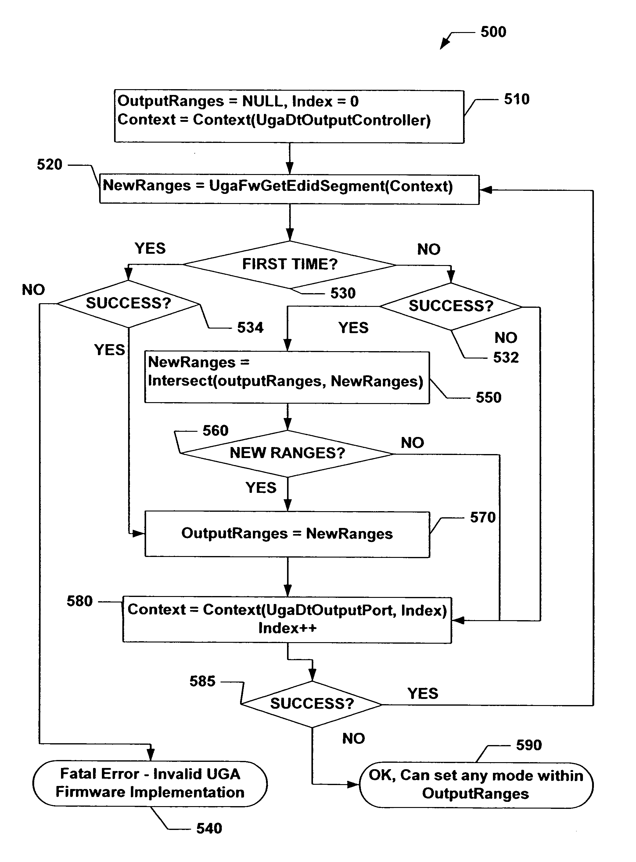
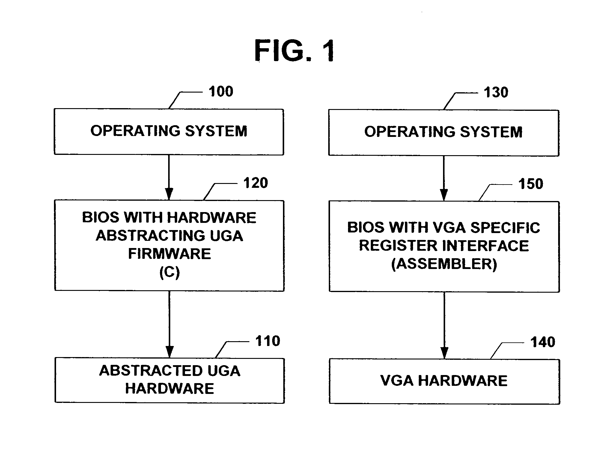
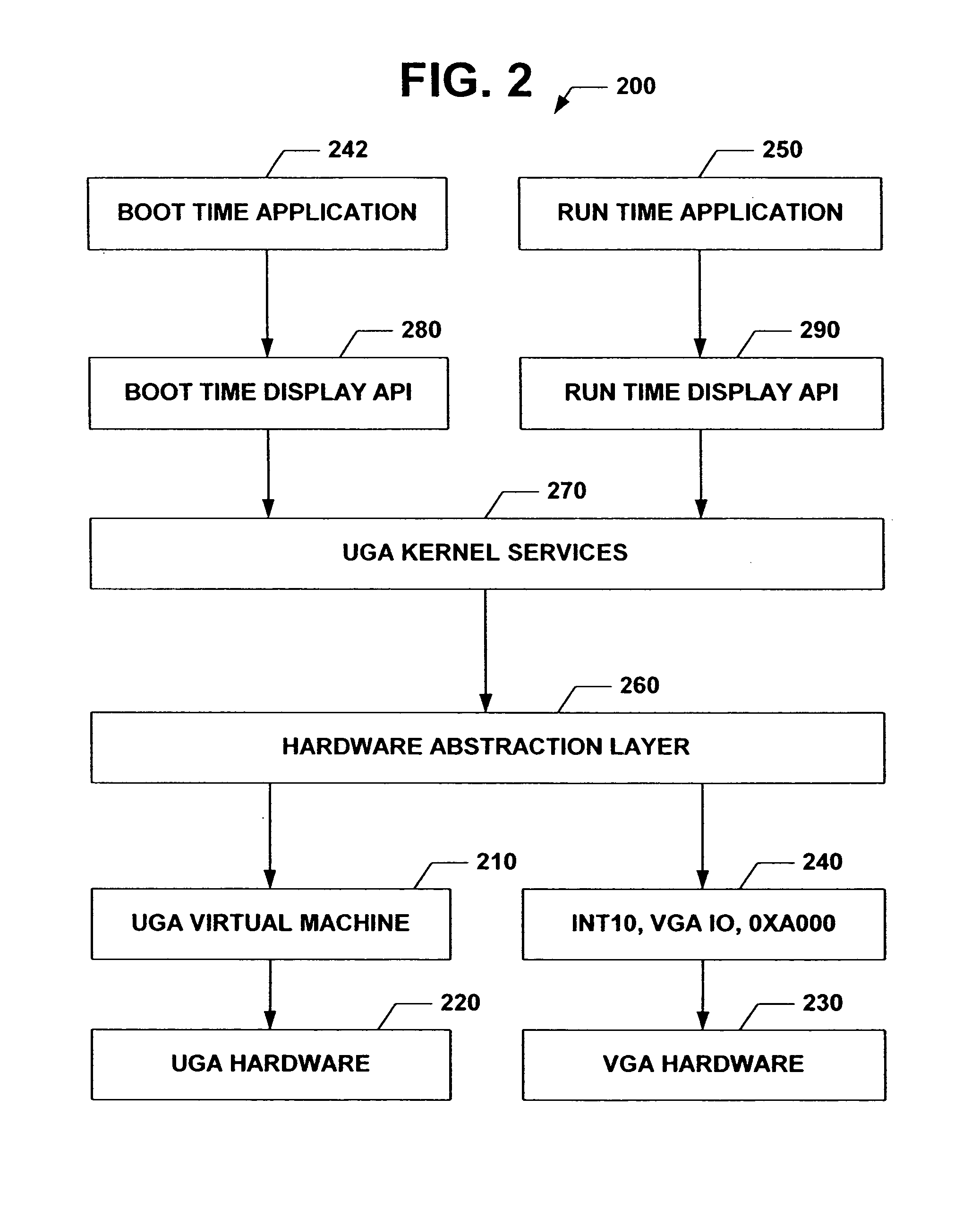
The subject invention relates to a Universal Graphics Adapter (UGA) that is a hardware-independent design that encapsulates and abstracts low-level graphics hardware in a standard manner through firmware. UGA is a firmware standard, intended to wrap existing or planned hardware, including VGA. UGA does not require the use of real-mode assembly language, direct hardware register, or frame buffer access to program, thus providing advantages over conventional systems. UGA supports basic drawing operations, continuous display modes, and power management. As a firmware-based standard, UGA facilitates updating a system to support both evolving and new hardware features.

Description

CROSS-REFERENCE TO RELATED APPLICATION[0001]This application is a divisional application of U.S. patent application Ser. No. 10 / 157,067 filed May 29, 2002, now U.S. Pat. No. 6,907,482 entitled UNIVERSAL GRAPHICS ADAPTER, which claims the benefit of U.S. Provisional Application Ser. No. 60 / 341,140 entitled UNIVERSAL GRAPHICS ADAPTER filed on Dec. 13, 2001 the entireties of which are incorporated herein by reference.TECHNICAL FIELD[0002]The present invention relates generally to video graphics display and more particularly to hardware independent video display facilitated through firmware services that abstract video hardware and expose an interface to an operating system.BACKGROUND OF THE INVENTION[0003]Video graphics array (VGA) is a graphics display system for personal computers (PCs). VGA has become one of the de facto standards for PCs, providing a resolution of 720 by 400 pixels in text mode and a choice of resolutions in graphics mode (e.g., 640 by 480 by 16 colors, 320 by 200 ...

Claims


Application Information

Patent Timeline
Patent Type & Authority Patents(United States)
IPC IPC(8): G06F3/00G06F13/00G06F9/445G06F13/12G06T17/00
CPCG06F3/14G06T15/005G06T17/00G09G5/363G09G5/006G09G2370/047G09G2370/042
Inventor MACIESOWICZ, MACIEJ
Owner MICROSOFT TECH LICENSING LLC
Learn More