Electrode tip dresser

a technology of electrode tip and dresser, which is applied in the direction of electrode maintenance, manufacturing tools, abrasive surface conditioning devices, etc., can solve the problem of inability to dress the electrode tip, and achieve the effect of suppressing the consumption of tip material, high accuracy, and suppressing the formation of swar

Inactive Publication Date: 2007-08-21
KYOKUTOH KOREA CORP
View PDF22 Cites 10 Cited by
  • Summary
  • Abstract
  • Description
  • Claims
  • Application Information

AI Technical Summary

Benefits of technology

[0011]An object of the present invention is to provide an electrode tip dresser which can dress a pair of electrode tips to a usable state while achieving a desired accuracy of a tip surface of each electrode tip including an angular portion at a peripheral edge of the tip surface, without separating each electrode tip from a welding gun.
[0027]The cutter may include restraining surfaces which are arranged at opposite sides of the cutting blade in the direction orthogonal to the axis of the associated support shaft, respectively, to restrain the enlarged diameter portion of the associated electrode tip, and thus, to prevent the associated electrode tip from joggling in the direction orthogonal to the axis of the electrode tip during a dressing process. Accordingly, even in the case in which the dressing rollers have a small outer diameter, it is possible to prevent the electrode tips from escaping from the outer peripheral surfaces of the dressing rollers when the electrode tips are pressed against the dressing rollers, respectively. This is because the electrode tips are restrained by the restraining surfaces of the cutters. Accordingly, it is possible to smoothly dress the electrode tips even when the dressing rollers are configured to have a small outer diameter in order to reduce the installation space of the electrode tip dresser.

Problems solved by technology

In other words, it is impossible to dress the electrode tip in a state in which the electrode tip is held in the welding gun.

Method used


Image

  • Electrode tip dresser
  • Electrode tip dresser
  • Electrode tip dresser

Examples


first embodiment

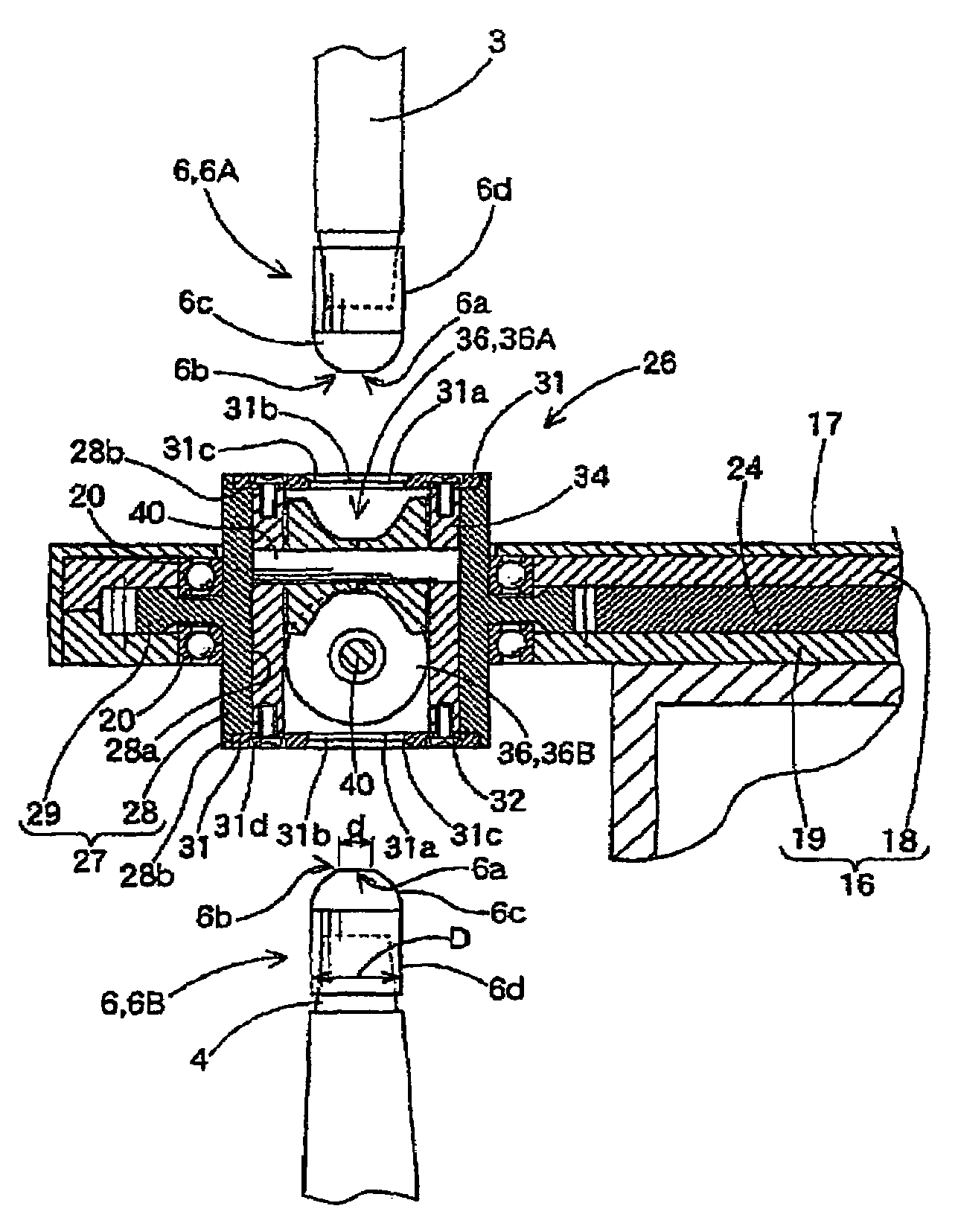
[0043]Each of the electrode tips 6A and 6B includes a tip section which contacts a work piece during a welding process, and a cylindrical shank section 6d. The tip section has a circular tip surface 6a, and an enlarged diameter portion 6c having a diameter increasing as the enlarged diameter portion 6c extends from a peripheral edge (angular portion) 6b of the tip surface 6a to the cylindrical shank section 6d. In the present invention, the enlarged diameter portion 6c has an approximately hemispherical shape. Also, the tip surface 6a has a diameter d of 6 mm, and the shank section 6d has a diameter D of 16 mm. The diameters d and D are indicated in FIG. 3.

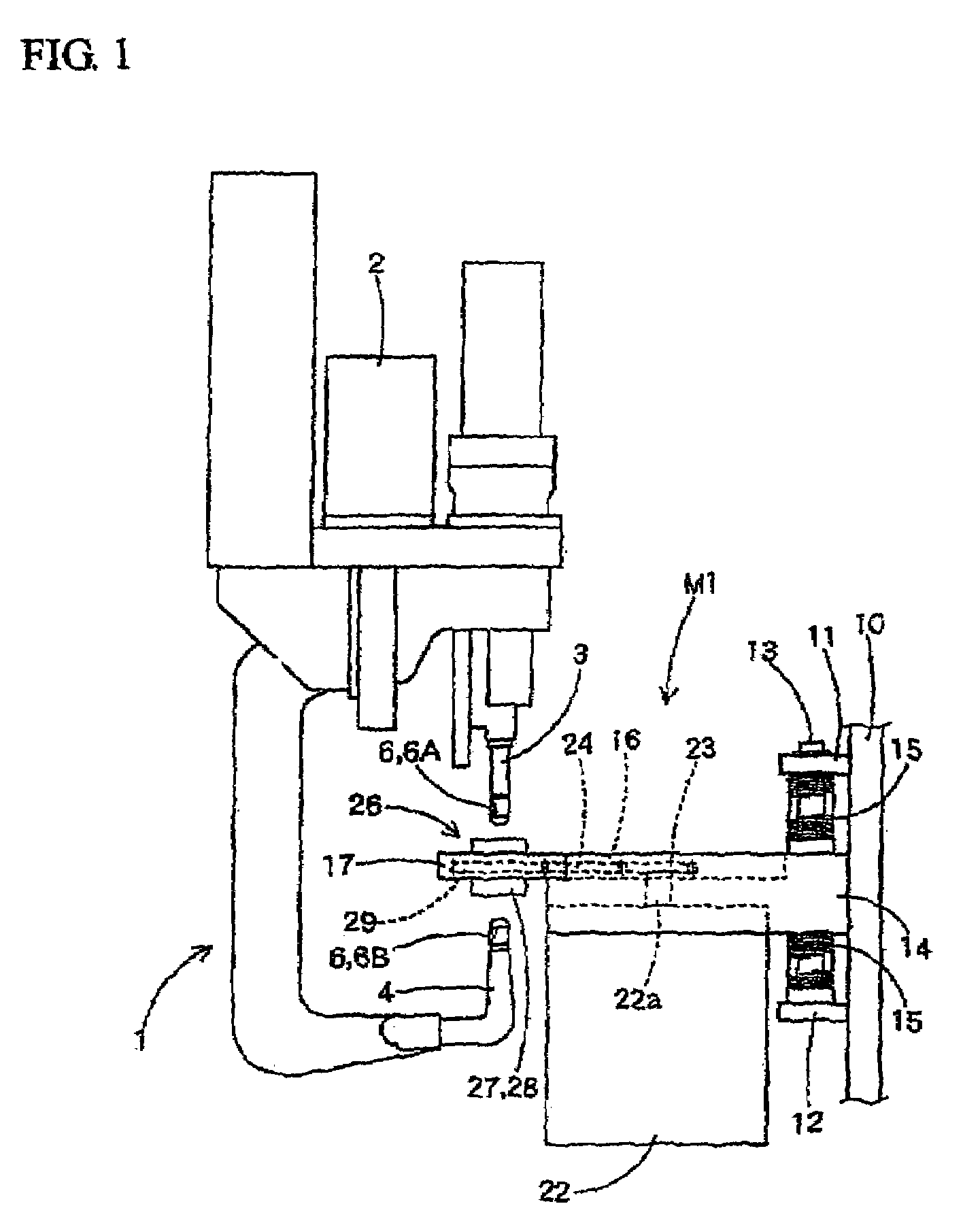
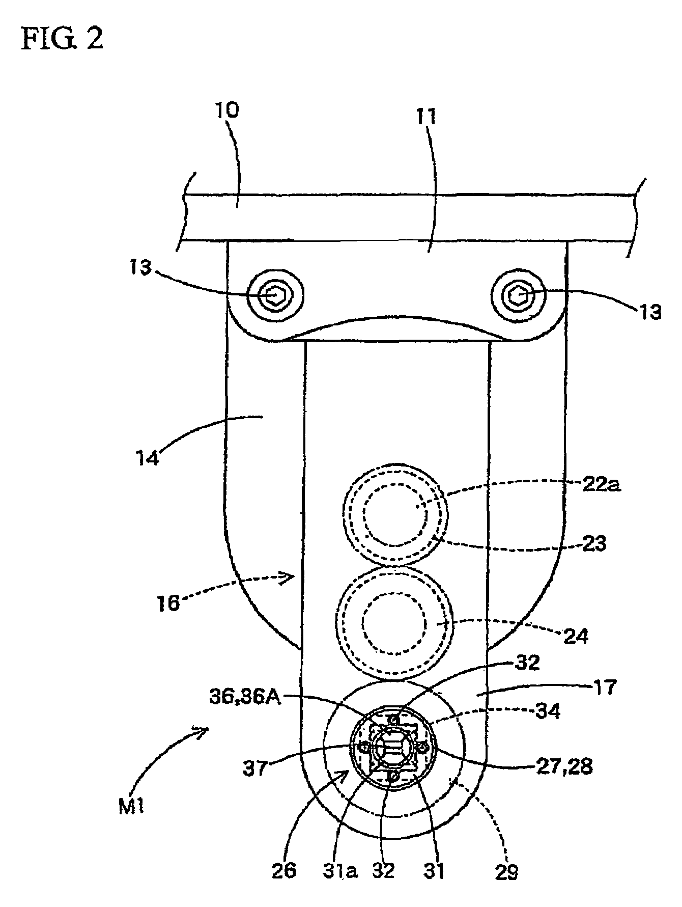
[0044]The electrode tip dresser M1 is arranged within a movement range of the servo gun 1 moved by operation of the welding robot. As shown in FIGS. 1 to 3, the electrode tip dresser M1 includes a support frame 10, a guide block 14, a gear case 16, a drive motor 222, and a dresser body 26.

[0045]Upper and lower brackets 11 and 12 a...

second embodiment

[0072]Referring to FIG. 8, an electrode tip dresser M2 according to the present is illustrated. The electrode tip dresser M2 includes a configuration in which cutters 50 are provided at a pair of dressing rollers 46, namely, dressing rollers 46A and 46B, included in a dresser body 26A, respectively.

[0073]Meanwhile, the configuration in the second embodiment of the present invention, except for the dressing rollers 46 of the dresser body 26A, namely, the configuration including the support shaft 40 for supporting each roller 46, the holder 34 for rotatably holding each support shaft 40, and the rotating barrel 27, is identical to those of the first embodiment of the present invention. Accordingly, the elements included in this configuration are designated by the same reference numerals as those of the first embodiment, respectively, and no description thereof will be given. Also, the configuration of the second embodiment, except for the dresser body 26A, namely, the configuration fo...


PUM

PropertyMeasurementUnit
diameteraaaaaaaaaa
diameteraaaaaaaaaa
inner diameteraaaaaaaaaa

Abstract

An electrode tip dresser is disclosed which can dress a pair of electrode tips to a usable state while achieving a desired accuracy of a tip surface of each electrode tip including an angular portion at a peripheral edge of the tip surface, without separating each electrode tip from a welding gun. The electrode tip dresser includes a holder which is rotatable about a common axis of electrode tips, a pair of support shafts which are held by the holder, are arranged in parallel in an approach direction of the electrode tips, and extend in a direction orthogonal to the approach direction, and a pair of dressing rollers which are rotatably supported by the support shafts, respectively, to dress the electrode tips to a usable state. Each dressing roller includes a groove which has a cross-section conforming to the outline of the tip section of the associated electrode tip when the cross-section is taken in a direction orthogonal to the associated support shaft, and the outline is taken after the dressing of the electrode tip. Each dressing roller includes two axially-divided roller bodies. The dividing plane of the divided roller bodies is arranged at the center of the tip surface of the associated electrode tip in a direction orthogonal to the axis of the associated electrode tip.

Description

[0001]This application claims the benefit of Korean Patent Application No. 2005-0116312, filed Dec. 1, 2005, which is hereby incorporated by reference as if fully set forth herein.BACKGROUND OF THE INVENTION[0002]1. Field of the Invention[0003]The present invention relates to an electrode tip dresser which dresses a pair of electrode tips held in a welding gun for spot welding while minimizing a grinding task inevitably involving formation of swarf.[0004]2. Discussion of the Related Art[0005]There are conventional electrode tip dressers which can dress electrode tips for spot welding while minimizing a grinding task involving formation of swarf. In such conventional electrode tip dressers, a die is used on which a deformed electrode tip is pressed so that the electrode tip is dressed (as disclosed in, for example, Japanese Patent Laid-open Publication Nos. 2004-167535 and 2001-138065).[0006]When an electrode tip is dressed using such an electrode tip dresser, it is possible to reduc...

Claims


Application Information

Patent Timeline
Patent Type & Authority Patents(United States)
IPC IPC(8): B23K11/30B23C1/00B23C3/12
CPCB23K11/3063Y10T29/5191Y10T409/3042Y10T409/304256B23K11/115B23K11/36B24B9/04B24B19/16B24B53/04
Inventor SHIM, DONG IL
Owner KYOKUTOH KOREA CORP
Why Eureka
Try Eureka