System, method, and apparatus for dual gas delivery through a high temperature artifact without undesirable gas mixing

a high temperature artifact and gas delivery technology, applied in the direction of machines/engines, gas-gas reaction processes, transportation and packaging, etc., can solve the problems of graphite porousness, inability to manufacture and assemble high temperature artifacts into a geometry that contains gas flow channels that do not allow gas mixing, and a significant obstacle to maintaining separation between the two gases with components fabricated from non-reactive materials, etc., to achieve the effect of reducing the risk and difficulty

Inactive Publication Date: 2007-08-21
POCO GRAPHITE
View PDF15 Cites 2 Cited by
  • Summary
  • Abstract
  • Description
  • Claims
  • Application Information

AI Technical Summary

Benefits of technology

[0007]One embodiment of a system, method, and apparatus for conveying two gases separately from each other to control delivery and gas mixing is disclosed. This design and manufacturing approach utilizes high temperature materials as components, such as graphite or silicon carbide (SiC). The present invention provides a producible manufacturing approach to meet functional requirements that overcome prior art engineering, design, and manufacturing issues relating to keeping two gases separate prior to mixing. By manufacturing flow channels for both gases into one component, the ring and spool design of the present invention minimizes the risk and difficulty of combining two seal technologies.
[0009]The spool has the appearance of two plates that are separated by a large number of integrally formed, spaced-apart columns. The second gas flows around the perimeter and through oval slots in the circumference of the spool between the plates before exiting the lower surface of the spool. The second gas is separated from the first gas by a material seal (e.g., coating) without the presence of a mechanical seal. The first gas flows through holes in the columns, which the second gas flows in channels and troughs between the columns. Thus, the first gas flows directly through spool from top to bottom, whereas the second gas flows and fills from the perimeter of the spool and through the columns before exiting the bottom of the spool. The circumference of the spool must be left open for access during manufacturing. The ring engages the spool to seal its open circumference (and interior) and prevent the escape of the second gas from the spool. Only the second gas contacts both the spool and the ring. The seal between the spool and the ring is mechanical, and any leaks therethrough does not cause mixing with the first gas.

Problems solved by technology

However, maintaining separation between the two gases with components fabricated from non-reactive materials is a significant obstacle for at least two reasons.
First, high temperature materials (such as graphite) are often porous and require a seal or coating to form a gas barrier.
Secondly, manufacturing and assembling high temperature artifacts into a geometry that contains gas flow channels that do not allow gas mixing has not been accomplished previously.
One of the greatest difficulties is sealing at the interfaces between components (e.g., a component-to-component seal).
Sealing technology for either type of these areas is significant, and sealing both types of areas together has eluded both design and manufacturing technology to date.
These devices simply cannot form high temperature seals for highly reactive gases.
When gas flow is used for chemical reaction to facilitate a process (e.g., semiconductor processing; especially etching), the difficulty often becomes that of handling and conveying the reactive chemical gases to the process area.

Method used


Image

  • System, method, and apparatus for dual gas delivery through a high temperature artifact without undesirable gas mixing
  • System, method, and apparatus for dual gas delivery through a high temperature artifact without undesirable gas mixing
  • System, method, and apparatus for dual gas delivery through a high temperature artifact without undesirable gas mixing

Examples


Embodiment Construction

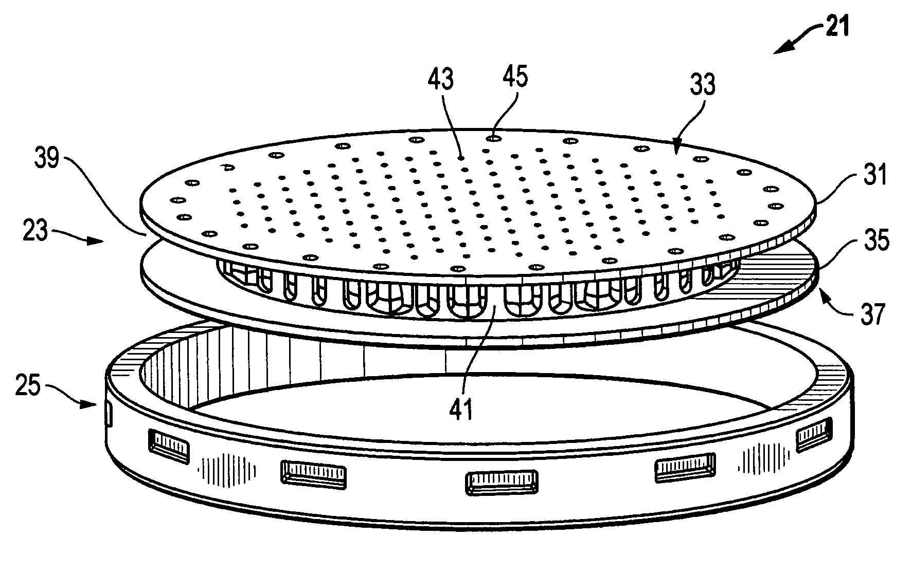
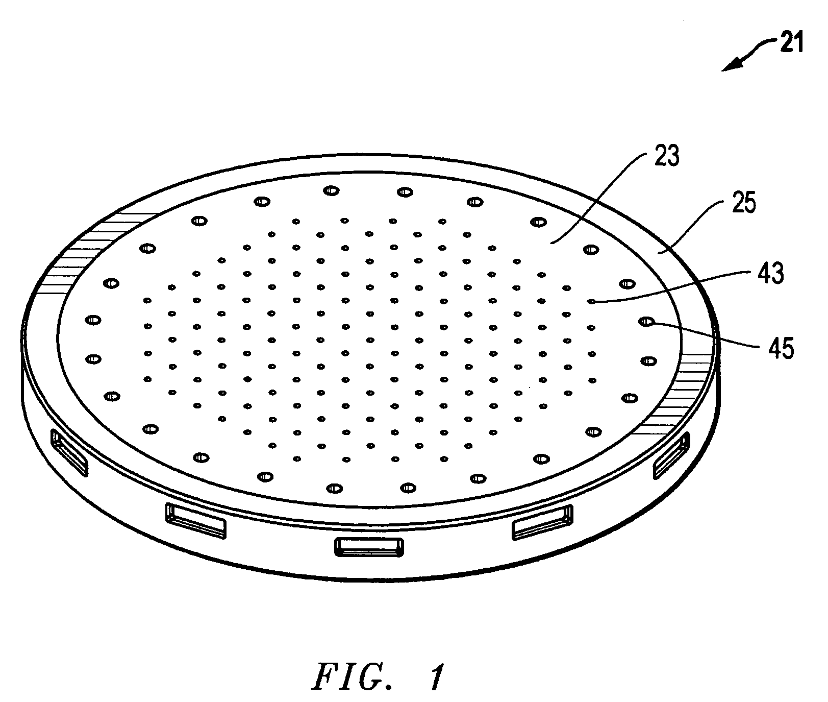
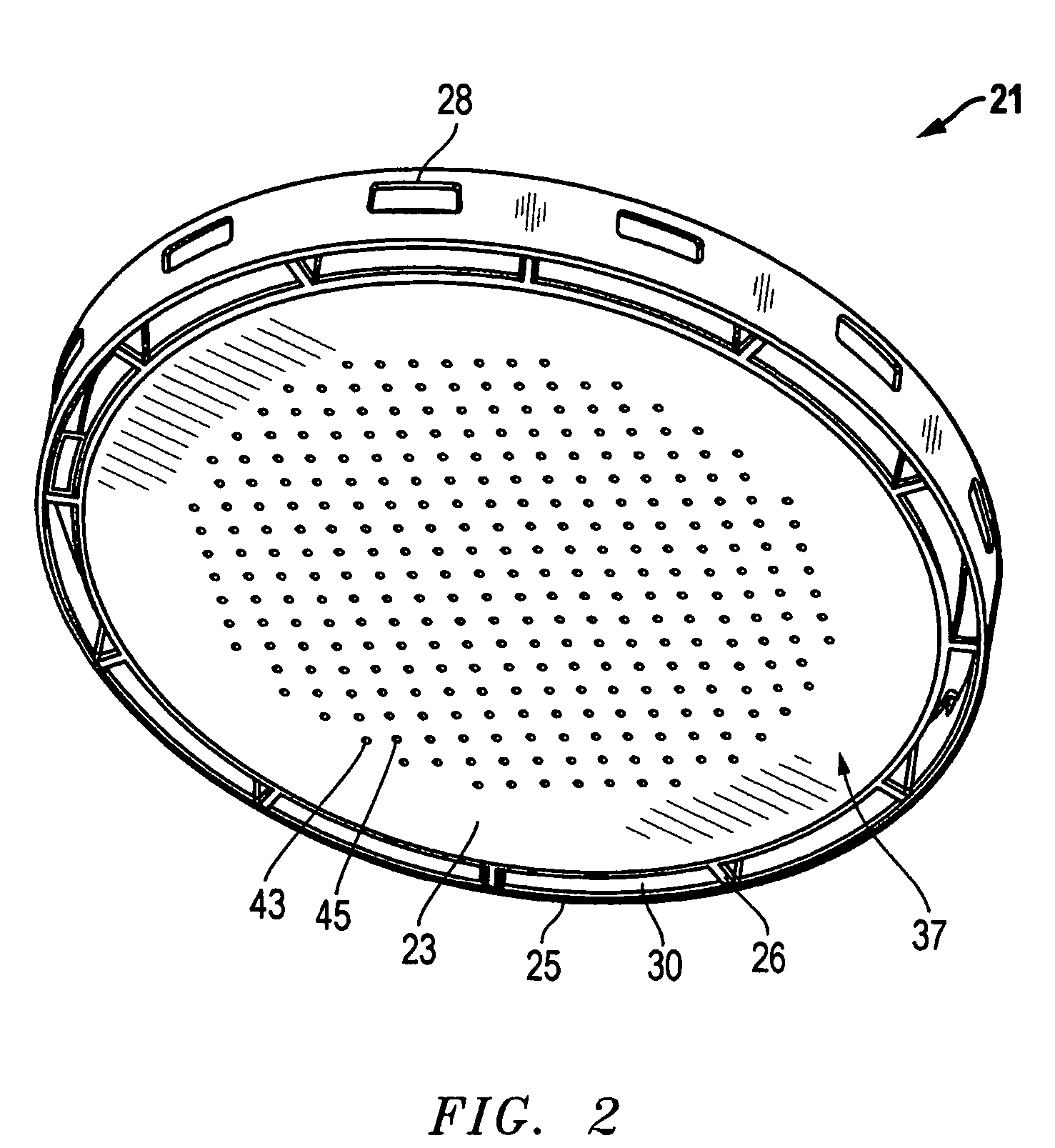
[0018]Referring to FIGS. 1-6, one embodiment of an apparatus, system, and method of separately conveying two gases through an apparatus or artifact 21 without mixing the gases as they are transmitted through the artifact is disclosed. The artifact 21 comprises two components 23, 25 that are preferably each machined separately or independently from a solid block of material to form two, completely integral structures. The first component 23 is a cylindrical spool having an inlet plate 31 (FIG. 3) with an inlet surface 33 and an outlet plate 35 with an outlet surface 37. The inlet and outlet plates 31, 35 are spaced apart from each other to define an interior having a perimeter 39 that is at least partially exposed to an exterior of the first component 23.

[0019]The first component 23 also has a plurality of integral posts or columns 41 extending between the inlet and outlet plates 31, 35 that are accessible from the perimeter for machining or fabrication purposes. In the embodiment sh...


PUM


Abstract

A system conveys two gases separately until controlled delivery and gas mixing are desired. The device maintains separation between the two gases with sealed, high temperature materials, and a geometry that contains gas flow channels that do not allow gas mixing. The present design provides a seal at the interfaces between components. An outer ring and an inner spool are assembled together to form a single component that accommodates the input of two, initially separate gases, and then contains and conveys the two gases separately to an exit surface where outlet holes allow the two gases to mix and react in a controlled manner upon exiting the component. The inlet holes for both gases are located on one side of the spool. The exit holes are formed in a centralized, alternating, completely interspersed array or grid-like pattern on the opposite surface of the spool.

Description

[0001]The present patent application claims the benefit of U.S. Provisional Patent Application No. 60 / 528,278, filed on Dec. 9, 2003, and is incorporated herein by reference.BACKGROUND OF THE INVENTION[0002]1. Technical Field[0003]The present invention relates in general to the controlled mixing of gases and, in particular, to an improved system, method, and apparatus for controlling the delivery of two gases through a high temperature artifact without undesirable mixing of the gases during transmission through the artifact.[0004]2. Description of the Related Art[0005]In some industrial applications, two gases must be mixed and reacted in a controlled atmosphere at very high temperatures. However, maintaining separation between the two gases with components fabricated from non-reactive materials is a significant obstacle for at least two reasons. First, high temperature materials (such as graphite) are often porous and require a seal or coating to form a gas barrier. This is a mater...

Claims


Application Information

Patent Timeline
Patent Type & Authority Patents(United States)
IPC IPC(8): F02G1/00B01J4/00B01J12/00B01J19/00B01J19/02
CPCB01J4/001B01J12/005B01J19/002B01J19/0073B01J19/02B01J2219/0263B01J2219/0272Y10T137/87281Y10T137/87652B01J4/00B01J12/00B01J19/00F02G1/00
Inventor PLUMMER, RONALD E.
Owner POCO GRAPHITE
Why Eureka
Try Eureka