
Microfluidic devices and methods of use

a microfluidic device and microfluidic technology, applied in the direction of fluid speed measurement, diaphragm, electrolysis, etc., can solve the problems of inability to work with conventional sorting procedures, inability to achieve gel electrophoresis, and relatively long gel electrophoresis procedures, so as to reduce the amplitude of oscillation pressure and lessen the oscillation of velocity of the entity

Inactive Publication Date: 2007-08-21
CALIFORNIA INST OF TECH
View PDF76 Cites 210 Cited by
  • Summary
  • Abstract
  • Description
  • Claims
  • Application Information

AI Technical Summary

Benefits of technology

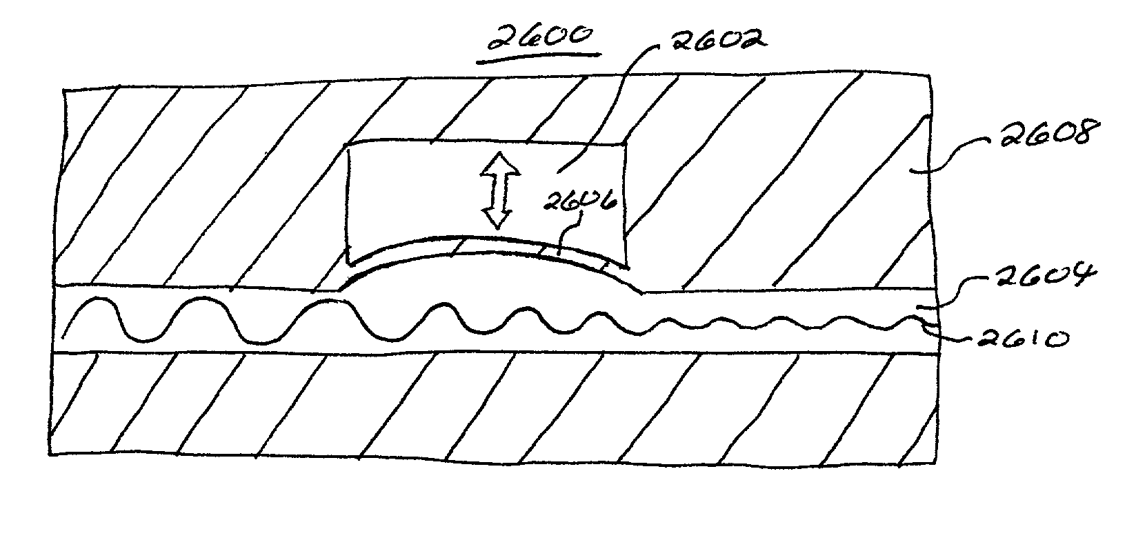
[0009]An embodiment of a microfluidic device in accordance with the present invention comprises pumps, valves, and fluid oscillation dampers. In a device employed for sorting, an entity is flowed by the pump along a flow channel through a detection region to a junction. Based upon an identity of the entity determined in the detection region, a waste or collection valve located on opposite branches of the flow channel is actuated, thereby routing the entity to either a waste pool or a collection pool. A damper structure may be located between the pump and the junction. The damper reduces the amplitude of oscillation pressure in the flow channel due to operation of the pump, thereby lessening oscillation in velocity of the entity during sorting process. The microfluidic device may be formed in a block of elastomer material, with thin membranes of the elastomer material deflectable into the flow channel to provide pump or valve functionality.
[0010]An embodiment of a microfluidic device in accordance with the present invention comprises a flow channel, a pump operatively interconnected to said flow channel for moving a fluid in said flow channel, and a damper operatively interconnected to said flow channel for reducing the fluid oscillation in said flow channel.

Problems solved by technology

While powerful, electrophoretic methods pose disadvantages.
For extremely large DNA molecules, the conventional sorting procedure is not workable.
Moreover, gel electrophoresis is a relatively lengthy procedure, and may require on the order of hours or days to perform.
However, this approach offers some important disadvantages.
One disadvantage is that the complexity, size, and expense of the sorting device requires that it be reusable in order to be cost-effective.
Reuse can in turn lead to problems with residual materials causing contamination of samples and turbulent fluid flow.
Another disadvantage of conventional sorting technologies is an inability to readily integrate sorting with other activities.
For example, due to the mechanical complexity of conventional sorting apparatuses, pre-sorting activities such as labeling and post-sorting activities such as crystallization are typically performed on different devices, requiring physical transfer of the pre- and post-sorted sample to the sampling apparatus.
Moreover, sample handling for conventional sorter structures is time-consuming.
The resulting delay may hinder analysis of materials having limited lifetimes, or prevent sorting that is based upon time-dependent criteria.

Method used


Image

  • Microfluidic devices and methods of use
  • Microfluidic devices and methods of use
  • Microfluidic devices and methods of use

Examples


Embodiment Construction

I. Microfabrication Overview

[0064]The following discussion relates to formation of microfabricated fluidic devices utilizing elastomer materials, as described generally in U.S. patent application Ser. Nos. 09 / 826,585 filed Apr. 6, 2001, 09 / 724,784 filed Nov. 28, 2000, and 09 / 605,520, filed Jun. 27, 2000. These patent applications are hereby incorporated by reference.

[0065]1. Methods of Fabricating

[0066]Exemplary methods of fabricating the present invention are provided herein. It is to be understood that the present invention is not limited to fabrication by one or the other of these methods. Rather, other suitable methods of fabricating the present microstructures, including modifying the present methods, are also contemplated.

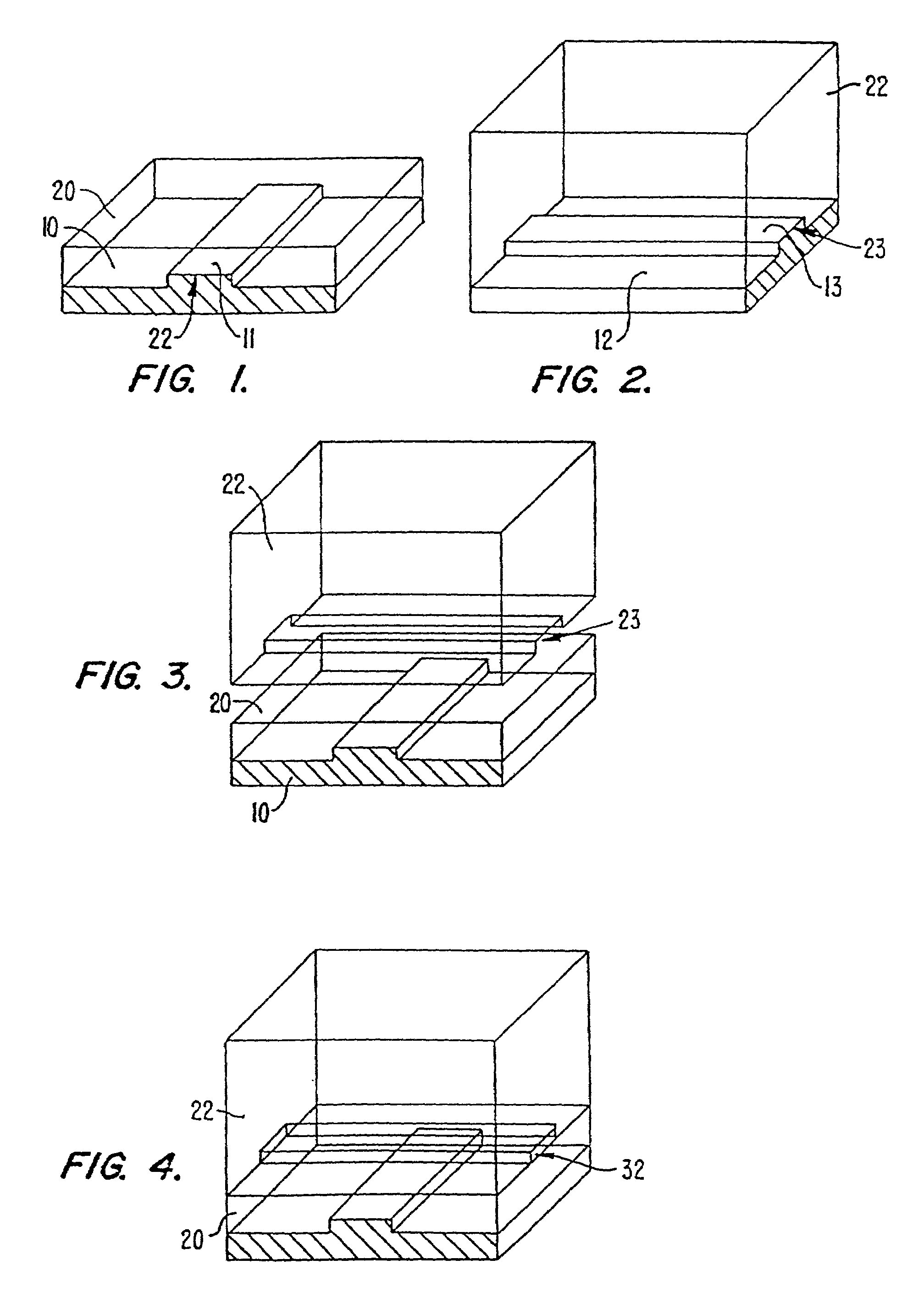
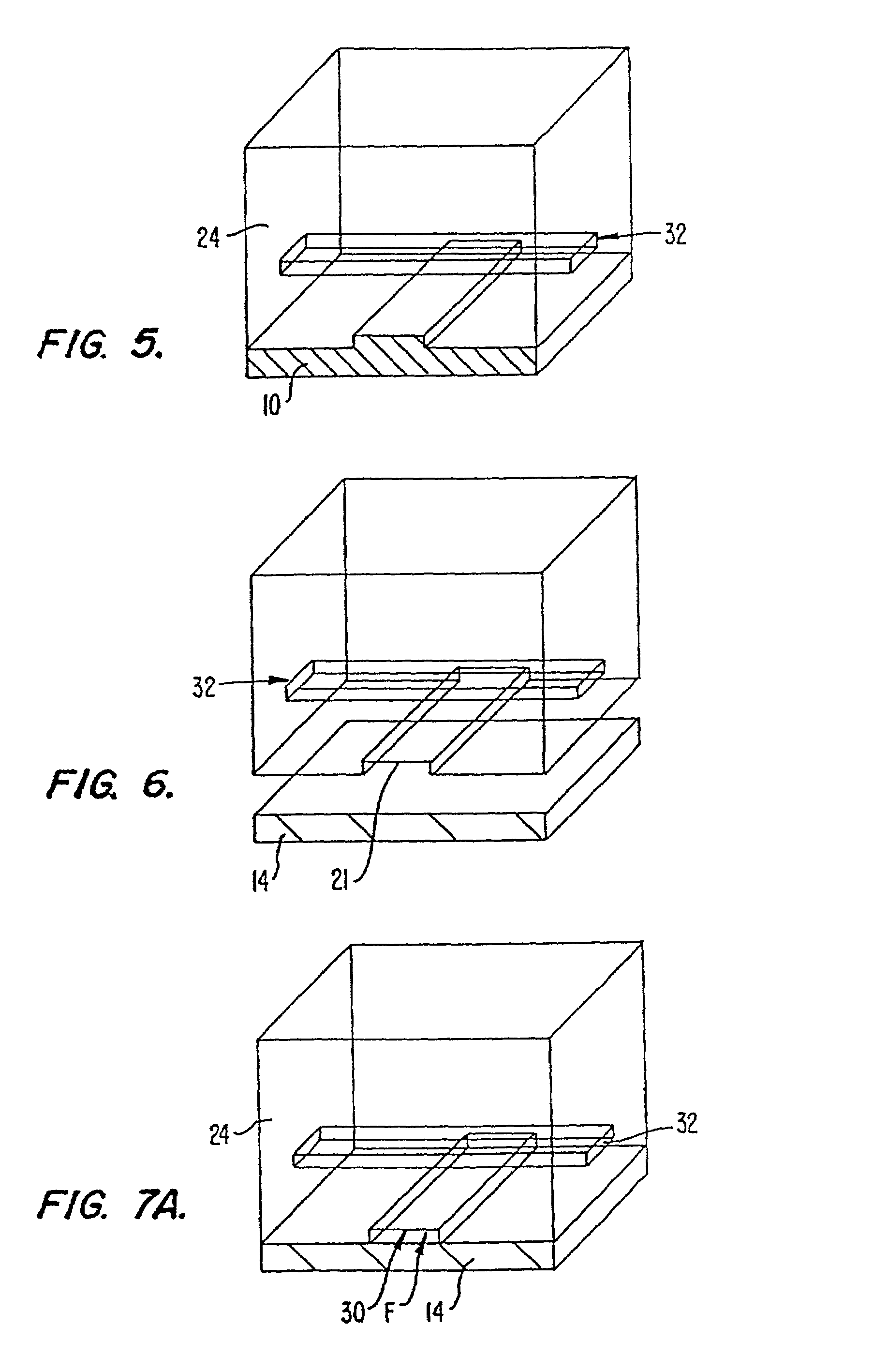
[0067]FIGS. 1 to 7B illustrate sequential steps of a first preferred method of fabricating the present microstructure, (which may be used as a pump or valve). FIGS. 8 to 18 illustrate sequential steps of a second preferred method of fabricating the present mi...


PUM

PropertyMeasurementUnit
widthsaaaaaaaaaa
widthsaaaaaaaaaa
widthsaaaaaaaaaa

Abstract

A microfluidic device comprises pumps, valves, and fluid oscillation dampers. In a device employed for sorting, an entity is flowed by the pump along a flow channel through a detection region to a junction. Based upon an identity of the entity determined in the detection region, a waste or collection valve located on opposite branches of the flow channel at the junction are actuated, thereby routing the entity to either a waste pool or a collection pool. A damper structure may be located between the pump and the junction. The damper reduces the amplitude of oscillation pressure in the flow channel due to operation of the pump, thereby lessening oscillation in velocity of the entity during sorting process. The microfluidic device may be formed in a block of elastomer material, with thin membranes of the elastomer material deflectable into the flow channel to provide pump or valve functionality.

Description

CROSS-REFERENCE TO RELATED APPLICATION(S)[0001]The instant nonprovisional patent application claims priority from U.S. Provisional Patent Application No. 60 / 237,938, entitled MICROFLUIDIC DEVICES AND METHODS OF USE, filed Oct. 3, 2000. The instant nonprovisional patent application also claims priority from U.S. Provisional Patent Application No. 60 / 237,937, entitled VELOCITY INDEPENDENT MICROFLUIDIC FLOW CYTOMETRY, filed Oct. 3, 2000. These provisional patent applications are incorporated by reference herein for all purposes.STATEMENT REGARDING FEDERALLY SPONSORED RESEARCH[0002]Work described herein has been supported, in part, by National Institute of Health grant HG-01642-02. The United States Government may therefore have certain rights in the invention.BACKGROUND OF THE INVENTION[0003]Sorting of objects based upon size is extremely useful in many technical fields. For example, many assays in biology require determination of the size of molecular-sized entities. Of particular imp...

Claims


Application Information

Patent Timeline
Patent Type & Authority Patents(United States)
IPC IPC(8): F04B43/00B01L99/00B01L3/00B81B1/00B81B3/00F04B11/00F04B19/00F04B43/04G01N15/14G01N30/20G01N30/32G01N30/60
CPCB01L3/50273B01L3/502738F04B11/00F04B19/006F04B43/043B01L3/5027A61M2206/22Y10T436/2575B01L2200/0647B01L2300/0816B01L2300/0864B01L2300/123B01L2400/0418B01L2400/0481B01L2400/0655B01L2400/084G01N30/6095G01N2015/1081G01N2015/149G01N2030/205G01N2030/322F04B43/14F04B43/00
Inventor CHOU, HOU-PUFU, ANNE Y.QUAKE, STEPHEN R.
Owner CALIFORNIA INST OF TECH
Learn More