Downhole Acoustic Emitter

Active Publication Date: 2019-07-25
FEDERALNOE GOSUDARSTVENNOE BJUDZHETNOE UCHREZHDENIE NAUKI INST FIZIKI METALLOV IMENI M N MIKHEEVA URALSKOGO OTDELENIJA ROSSIJSKOJ AKADI NAUK IFM URO RAN +2
View PDF2 Cites 2 Cited by
  • Summary
  • Abstract
  • Description
  • Claims
  • Application Information

AI Technical Summary

Benefits of technology

[0021]The connection of the reference housing with the acoustic waveguide by means of a threaded connection increases the maintainability of the borehole acoustic waveguide by means of a threaded connection increases the maintainability of the borehole acoustic emitter in case of its damage, which is especially important in field conditions at wells.
[0022]Thus, the technical resul

Problems solved by technology

The supply of high-frequency power to the indicated emitters from the ground generator via a connecting geophysical cable leads to the use of these frequencies in the cable 50% of the energy for high-frequency heating, and, consequently, a sharp drop in system efficiency.
The diameter of modern oil producing wells allows positioning of the active elements of the emitters only along the axis of the well, and, therefore, the radiation from the end surfaces of the emitters, which have a small area, is directed in the axial direction, which also reduces the effectiveness of acoustic effects.
A disadvantage of this device is that the radiation from the end surfaces of the radiator occurs in the axial direction, and is also shielded by the housing.
As a result, this device has a small radius of effective impact on the bottomhole zone.
In addition, the use of a pressure compensator in the design of a bellows, reduces the reliability of the device, since a direct impact on the bellows of the acoustic field can damage the bellows mount and damage it.
A disadvantage of this device is that the radiating surface also has a small area and works in the axial direction, which reduces the radius of the effective impact of the downhole acoustic emitter on the bottomhole zone.
Another disadvantage of this device is the presence

Method used


Image

  • Downhole Acoustic Emitter

Examples


Example

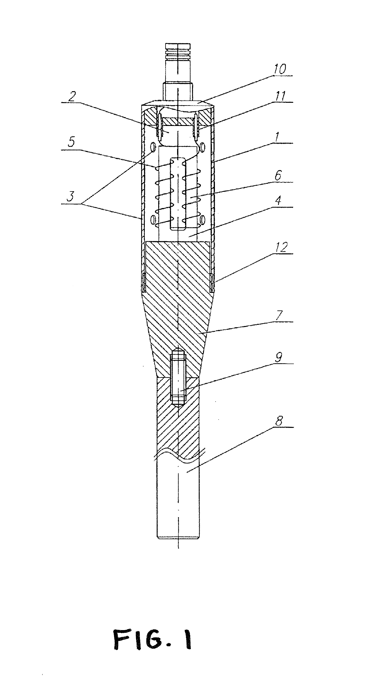
[0024]A downhole acoustic emitter contains an open support housing 1, with a cavity 2 and windows 3. A rod magnetostrictive transducer 4 with electric windings 5 on rods 6 is located within the cavity 2 of the housing 1. The downhole acoustic emitter also includes an acoustic waveguide 7, the upper end surface of which is coaxially connected to the lower radiating surface of the magnetostrictive transducer 4 by soldering. The acoustic waveguide 7 is made in the form of a cylinder, which passes into a decaying cone, while the cylindrical part of the acoustic waveguide 7 is located in the support housing 1 and the conical part is located outside the support housing 1. The lower end of the acoustic waveguide 7 is attached to the upper end of the radiating element 8 by a threaded connection 9. The radiating element 8 is made in the form of a cylinder or a prism with a square cross section. A standard geophysical end 10 of the brand NK-36 is installed in the support housing 1 to connect ...


PUM


Abstract

A downhole acoustic emitter including a support housing with a cavity and ports, in which housing are disposed a rod-type magnetostrictive transducer with an electrical coil on the rods, and an acoustic waveguide in the form of a cylinder which transitions into a tapering cone. The cylindrical portion of the acoustic waveguide is disposed inside the support housing, and the conical portion is disposed outside the housing. The upper end surface of the acoustic waveguide is coaxially joined to the lower emitting surface of the magnetostrictive transducer by soldering, and the acoustic waveguide is joined at its middle portion, which coincides with the zero vibration point of the waveguide, to the support housing by a threaded joint. The downhole acoustic emitter is provided with an emitting element, the upper end of which is coaxially joined to the lower end of the acoustic waveguide by a threaded joint. The magnetostrictive transducer has a length of 200-280 mm and is made of Permendur, and the ports are arranged around the perimeter of the support housing in two rows, the first of which is level with the top turns of the electrical coil of the magnetostrictive transducer, and the second row is level with the bottom turns of the coil. The emitting element is in the form of a cylinder or a prism with a square cross-section.

Description

BACKGROUND OF THE INVENTION1. Field of the Invention[0001]The invention relates to the oil industry and is intended to impact on the bottom zone of oil wells.2. Description of the Related Art[0002]Work on the application of acoustic effects on productive formations of oil wells and injection wells has been conducted since 1986, and several structures are currently known that create such an impact. In the course of these works, it was shown that the enhanced oil recovery of the fields directly depends on the increase in the effective radius of the downhole acoustic emitter on the bottom hole zone of the oil wells.[0003]Currently known designs of downhole emitters use operating frequencies of 20-30 Hz, which implies a fairly rapid attenuation of the acoustic wave in the near-well space. The supply of high-frequency power to the indicated emitters from the ground generator via a connecting geophysical cable leads to the use of these frequencies in the cable 50% of the energy for high-f...

Claims


Application Information

Patent Timeline
IPC IPC(8): E21B43/00B06B1/08H01L41/20E21B28/00
CPCE21B43/003B06B1/08H01L41/20E21B28/00B06B2201/73E21B43/25B06B3/00H10N35/85
Inventor VIKTOROVICH, TARAKANOV VALERIYINNOKENTYEVICH, KUZNETTSOV MIKHAILPETROVICH, PATSERKOVSKY ROMAN
Owner FEDERALNOE GOSUDARSTVENNOE BJUDZHETNOE UCHREZHDENIE NAUKI INST FIZIKI METALLOV IMENI M N MIKHEEVA URALSKOGO OTDELENIJA ROSSIJSKOJ AKADI NAUK IFM URO RAN
Why Eureka
Try Eureka