RF coil for a highly uniform B1 amplitude for high field MRI

a high-field mri, highly uniform technology, applied in the direction of diagnostic recording/measuring, using reradiation, instruments, etc., can solve the problems of difficult to obtain a highly uniform 180° pulse through a large 3d sample volume, hampered current high-field mri technology, and b of non-uniform b. to achieve the effect of improving the homogeneity of rf excitation and uniform magnetic field

Inactive Publication Date: 2007-08-21
BAYLOR COLLEGE OF MEDICINE
View PDF5 Cites 7 Cited by
  • Summary
  • Abstract
  • Description
  • Claims
  • Application Information

AI Technical Summary

Benefits of technology

[0006]The present invention is directed to an improved device and method for magnetic resonance imaging of tissue using an excitation array coil to produce a uniform magnetic field. The use of parallel excitation with an array of composite excitation elements containing current loops for generating the B1z field and current loops for independently shaping B1x and B1y fields is used to improve the homogeneity of RF excitation. For a lossless uniform medium, homogeneous transverse B1 amplitude distribution in a 3D volume is allowed by Maxwell's equations. For a lossy medium, plane-wise homogeneous transverse B1 amplitude is allowed. Using computer simulations, we have demonstrated that uniform RF amplitude in a 3D lossless and uniform medium can be obtained with the coils transmitting from inside the medium. We also demonstrate the use of this type of array coil under more realistic situations, where we transmit the RF power from air to a human head model in computer simulations employing the finite-difference time-domain numerical method. We construct analytic target B1 field patterns with plane-wise uniform (equivalent to in-plane uniform in our terminology) transverse B1 amplitude from the RF field generated by individual current loops. Therefore, we have shown the feasibility of this approach when applied to imaging human anatomy.

Problems solved by technology

However, current high-field (static field B0 strength approximately 1.5 T and higher) MRI technology is hampered by non-uniform B, amplitude distribution offered by conventional coil techniques.
Consequently, it has been very difficult to obtain a highly uniform 180° pulse through a large 3D sample volume.
Due to the short wavelength of the RF field inside the tissue, the field distribution is strongly affected by the shape of the object, and conventional hardware configurations do not provide optimal results at very high field strengths.
Due to the short wavelength of the RF field inside the tissue, the field distribution is strongly affected by the shape of the object, and conventional hardware configurations are unable to provide optimal results at very high field strengths.

Method used


Image

  • RF coil for a highly uniform B1 amplitude for high field MRI
  • RF coil for a highly uniform B1 amplitude for high field MRI
  • RF coil for a highly uniform B1 amplitude for high field MRI

Examples


example

[0051]Using computer simulation, we demonstrate the application of the present invention using an array coil configuration on a human head model. However, the invention is not limited to the human head application demonstrated below.

Array Coil Configuration

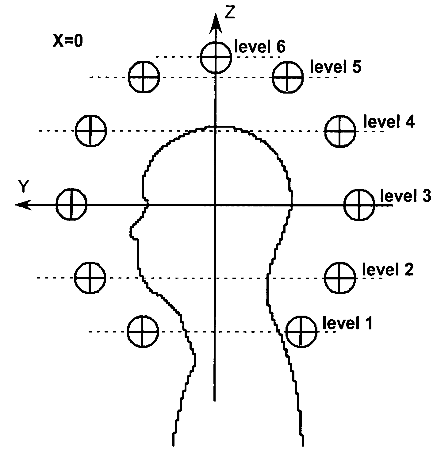
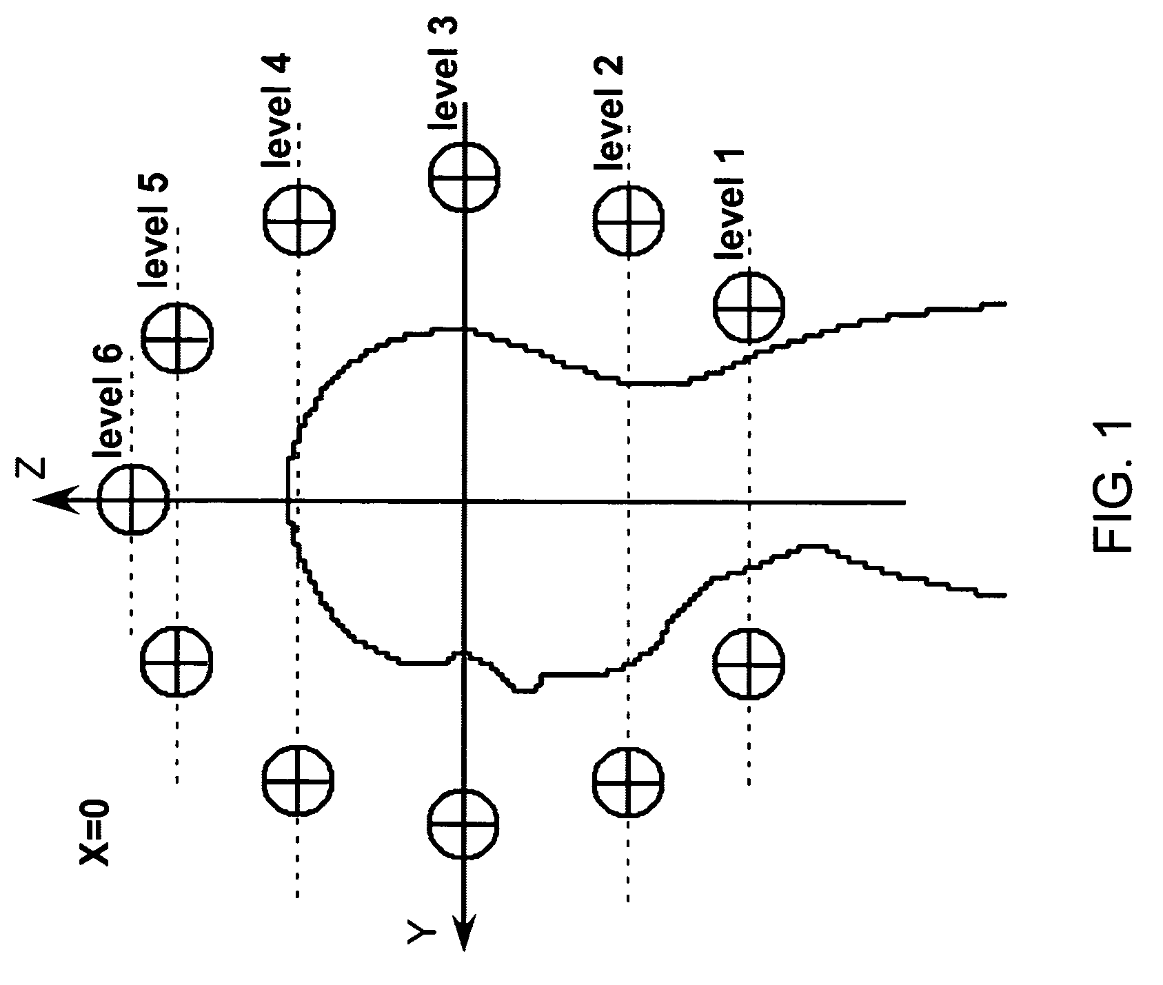
[0052]The transmit array consisted of 49 “composite excitation elements,” each having three orthogonal circular current loops with axes parallel to the x, y and z directions, respectively. The diameter of each current loop was 4.7 cm. The center positions of all three loops in one composite excitation element were the same. The array transmitted from the air. The locations of the coils are listed in Table 1 and also demonstrated in FIG. 1 for the elements on the yz-plane. The B0 field was along the z direction, and the positive z direction was from feet to head. The anterior aspect of the head corresponded to the positive y direction. The current loops were distributed at 6 different z levels. For Levels 2 through 6, the centers o...


PUM


Abstract

An array coil to achieve more uniform RF excitation for high field magnetic resonance imaging. In the preferred embodiment, the array coil has a plurality of transmit-composite elements distributed around the object to be imaged. A composite element comprises up to three current loops preferably orthogonal to each another. The array coil has the capability to shape the distribution of all three orthogonal components (x, y, and z) of the RF B1 field.

Description

CROSS-REFERENCE TO RELATED APPLICATIONS[0001]This application claims priority to U.S. application Ser. No. 60 / 652,274 filed on Feb. 11, 2005 and to U.S. application Ser. No. 60 / 679,804 filed on May 11, 2005.TECHNICAL FIELD[0002]The invention is directed to an improved device and method for magnetic resonance imaging (MRI) of the brain or other body parts using an excitation array coil to produce a uniform B1 field. Specifically, it is directed to a coil system for transmitting radio frequency magnetic field (B1 field) in magnetic resonance imaging scanners.BACKGROUND OF THE INVENTION[0003]The trend of development of MRI technology has been to use magnets of increasing strengths. However, current high-field (static field B0 strength approximately 1.5 T and higher) MRI technology is hampered by non-uniform B, amplitude distribution offered by conventional coil techniques. At high B0 field strengths the size of the human brain or other body parts is no longer small in comparison to the...

Claims


Application Information

Patent Timeline
Patent Type & Authority Patents(United States)
IPC IPC(8): G01V3/00
CPCG01R33/3415
Inventor WANG, ZHIYUE J.WANG, DAH-JYUU
Owner BAYLOR COLLEGE OF MEDICINE
Why Eureka
Try Eureka