Asynchronous sample rate converter and method

a sample rate converter and sample rate technology, applied in the field of sample rate converters, can solve the problems of undesirable/annoying sample dropping or sample repeating, high undesirable audible “popping or clicking” sound, and the use of analog phase locked loop circuits usually requires substantially more silicon chip area

Active Publication Date: 2007-08-28
TEXAS INSTR INC
View PDF8 Cites 40 Cited by
  • Summary
  • Abstract
  • Description
  • Claims
  • Application Information

AI Technical Summary

Benefits of technology

[0011]It is an object of the present invention to provide an asynchronous sample rate converter and method that provides precise phase matching between the input and output sampling times.

Problems solved by technology

However, sample rate converters are necessary for interfacing between devices receiving and / or producing digital signals having different sample rates in order to avoid audio sample dropping or sample repeating, which results in highly undesirable audible “popping” or “clicking” sounds.
Then, even though the nominal sample rates both are 48 kHz, a very small drift or difference between the frequencies of the above-mentioned clock signals will accumulate and cause the above-mentioned undesirable / annoying sample dropping or sample repeating if a synchronous sample rate converter is used.
Furthermore, use of analog phase locked loop circuits usually requires substantially more silicon chip area than would be required if digital techniques were used instead for the same purpose.
This has the disadvantage that the overall group delay of the asynchronous sample rate converter is greater than necessary in cases in which there is no aliasing for down-sampling.
Another prior asynchronous sample rate converter marketed by Analog Devices Inc. has only one stage for interpolation, which makes it difficult to achieve large attenuation of images with a reasonable filter length.
This may cause a substantial of amount of phase mismatch for multiple parallel-running asynchronous sample rate converters even when they are put into a matched phase mode wherein one asynchronous sample rate converter is set as a master and the rest are set as slaves.
How well the phase match is accomplished depends on how much information is transferred, and the bandwidth of the audio serial interface may limit the amount of information that can be transferred by the Analog Devices asynchronous sample rate converters.

Method used


Image

  • Asynchronous sample rate converter and method
  • Asynchronous sample rate converter and method
  • Asynchronous sample rate converter and method

Examples


Embodiment Construction

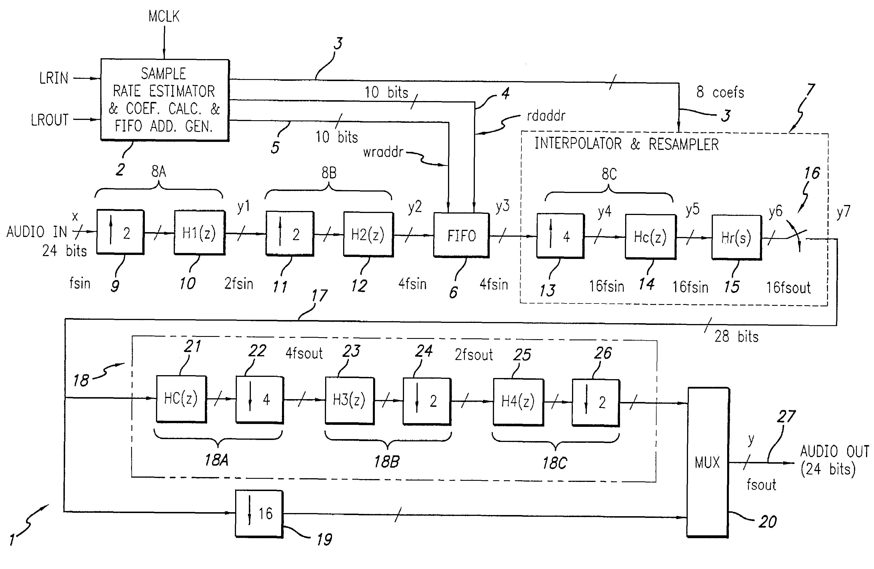
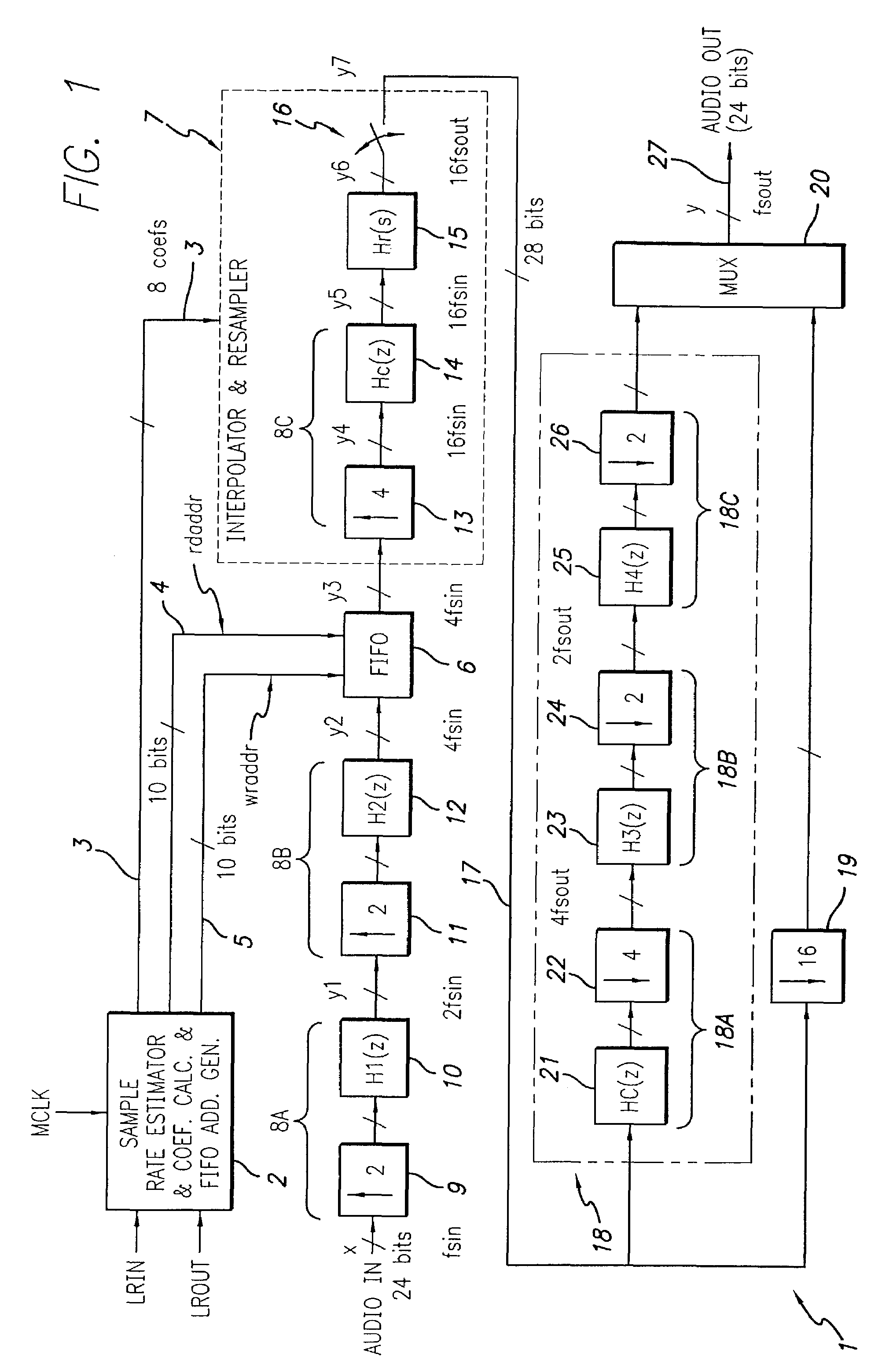
[0036]The described embodiment of the asynchronous sample rate converter 1 of the present invention as shown in the drawings is designed to operate within a range of the ratio between the input sample rate the and output sample rate from 1:16 to 16:1. Thus, asynchronous sample rate converter 1 has the capability of converting between any sample rates of Audio In (also designated by “x”) and Audio Out (also designated by “y”) in the range of, for example, 12 kHz to 192 kHz. Audio In, also designated by “x” in FIG. 1, is an already-digitized 24-bit version of an analog signal, and has a sample rate of fsin. Greatly simplified, an asynchronous sample rate converter can be considered to include only two main sections. The first section is to convert the signal from discrete-time to continuous-time, which is what is accomplished from the discrete-time signal Audio In to continuous-time signal y6 in FIG. 1. The second section just re-samples (but does not hold) the continuous-time signal ...


PUM


Abstract

An asynchronous sample rate converter interpolates and filters a digital audio input signal to produce a filtered, up-sampled first signal. A FIFO memory receives the first signal and stores samples thereof at locations determined by a write address and presents stored samples from locations determined by a read address. The presented samples are passed through an interpolation and resampling circuit to produce a continuous-time signal which is re-sampled to produce a signal that is up-sampled relative to a desired output. That signal then is filtered and down-sampled to produce the output signal. Sample rate estimating circuitry computes a difference signal representative of a time at which a data sample of the audio input signal is received and a time at which a corresponding audio output sample is required, and address generation circuitry generates the read and write addresses. A coefficient calculation circuit calculates filter coefficients for the interpolation and resampling circuit in response to the difference signal.

Description

BACKGROUND OF THE INVENTION[0001]The present invention relates generally to sample rate converters, and more particularly to asynchronous sample rate converters and methods.[0002]The digital audio format has become more and more popular for use in most audio signal applications, especially in applications for audio recording studios. In audio recording studios, various analog audio sources often are sampled at various different sample frequencies and then are digitized to produce various digital audio signals. In the digital format, the audio signals can be edited, reproduced and processed easily without introducing nearly as much distortion and noise as would be introduced if the same the same editing, reproducing and processing were to be performed on the same audio signals in analog format.[0003]However, sample rate converters are necessary for interfacing between devices receiving and / or producing digital signals having different sample rates in order to avoid audio sample dropp...

Claims


Application Information

Patent Timeline
Patent Type & Authority Patents(United States)
IPC IPC(8): H03M7/00H03H17/06
CPCH03H17/0628
Inventor YU, XIANGGANGSCULLEY, TERRY L.CHANG, JUNG-KUEI
Owner TEXAS INSTR INC
Why Eureka
Try Eureka