Flywheel hub-to-rim coupling

a hub and rim technology, applied in the direction of couplings, mechanical actuator clutches, mechanical equipment, etc., can solve the problems of high cost, difficult development of strain matching hubs, and large expansion of outer diameters, and achieve low cost, high radial growth, and low modulus

Inactive Publication Date: 2007-09-04
TORAY COMPOSITES (AMERICA) INC
View PDF27 Cites 20 Cited by
  • Summary
  • Abstract
  • Description
  • Claims
  • Application Information

AI Technical Summary

Benefits of technology

[0010]Accordingly, this invention provides a flywheel system having a composite flywheel rim that allows for use of low modulus, low cost fiber that has high radial growth of the inside diameter of the rim. The invention includes the use of a rim liner inside the flywheel rim that provides half of a sliding joint with the hub to be attached to the composite rim. This liner contains either holes for radial pins that match pin holes on t

Problems solved by technology

This large strain would make the development of a strain matching hub very difficult.
This type of hub can handle the centrifugal forces from high speed rotation however the growth of the outer diameter is very small.
Both of these strain-matching methods are expensive either because of use of very expensive high modulus carbon fibers or because of excessive and inefficient use of intermediate modulus carbon fiber.
The problem with these types of hubs is that they also require excess carbon fiber in the

Method used


Image

  • Flywheel hub-to-rim coupling
  • Flywheel hub-to-rim coupling
  • Flywheel hub-to-rim coupling

Examples


Embodiment Construction

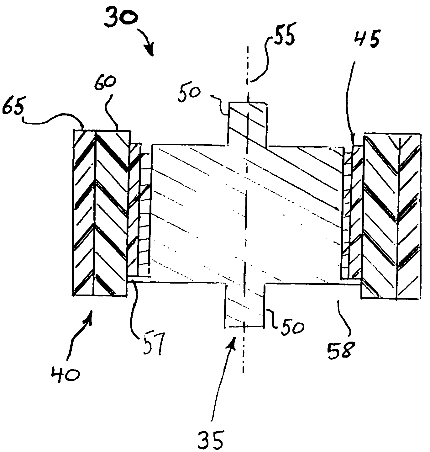
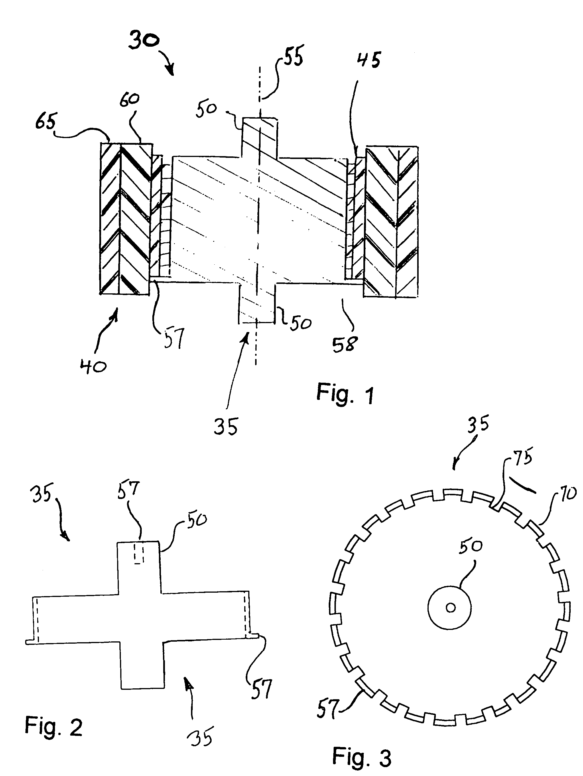
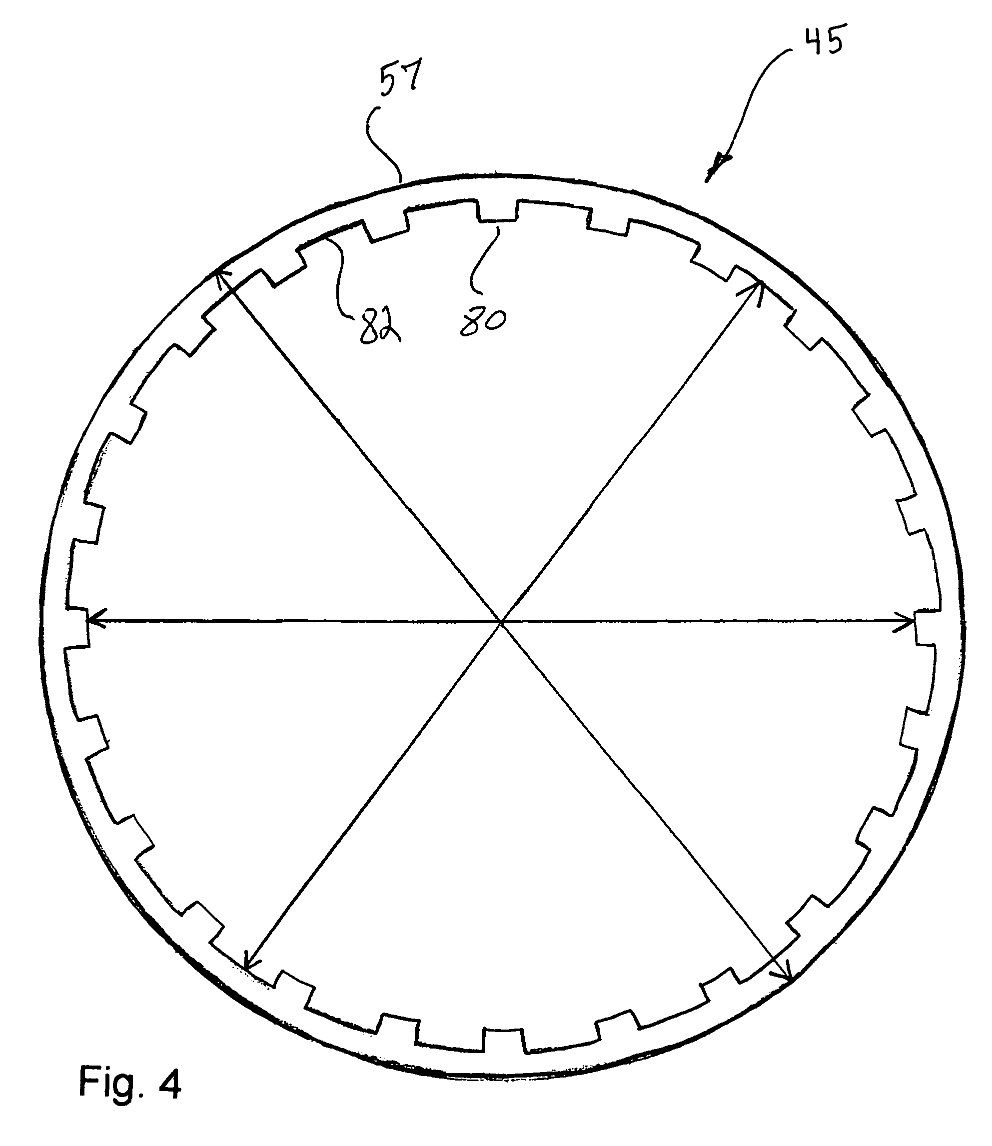
[0025]Turning now to the drawings, wherein like reference characters designate identical or corresponding parts, and more particularly to FIG. 1 thereof, a flywheel system 30 is shown having a hub 35, shown in FIGS. 2 and 3, and a rim 40 mounted on the hub by way of a rim liner 45, shown in FIG. 4. The hub 35, has a pair of stub shafts 50 projecting axially along an axis of rotation 55 for journaling the hub for high speed rotation in magnetic bearings within a vacuum chamber and ballistic container (not shown). An axial bore 57 may be provided for a quill shaft (not shown) for coupling to other elements in the flywheel system, as is known in the art. Other structures for supporting the hub 35 in the vacuum chamber for high speed rotation can also be used, as is well known in the flywheel industry. An electric motor / alternator is coupled to the hub 35 for initially driving the flywheel up to speed, and then recovering the energy, stored in the flywheel as rotational inertia, by conv...


PUM


Abstract

A flywheel system includes an annular rim mounted for high speed rotation on a flywheel hub. The hub has a radially splined exterior surface facing radially outwards. The rim includes an annular rim liner having an axis of rotation coinciding with the axis of rotation of the hub, and having an inner surface facing radially inward. The inner surface of the rim liner has integral splines projecting radially inward and extending axially. The rim liner splines mate with the hub splines. The flywheel rim liner has a modulus of elasticity el, and a density ρl, and a liner ratio Rl equal to Ell. The flywheel rim has a modulus of elasticity er in the hoop direction and a density ρr; and a rim ratio Rr equal to Err. The materials and configuration of the rim and rim liner are designed so that Rl is less than or equal to Rr, so said flywheel rim liner grows radially with the rim.

Description

[0001]This is related to U.S. Provisional Application 60 / 149,945 filed on Aug. 19, 1999 and entitled “Flywheel Hub-to-Rim Coupling”.[0002]This invention pertains to a hub-to-rim coupling system for high speed composite flywheels, and more particularly to a flywheel hub-to-rim coupling that accommodates radial growth of the flywheel rim in operation without decoupling from the hub.BACKGROUND OF THE INVENTION[0003]Flywheels have been used for many years for storing energy in a system, and then releasing that stored energy back into the system. They provide a smoothing effect for internal combustion engines and many kinds of power equipment. More recently, modern flywheel systems have become recognized as very attractive energy storage systems in electrical applications such as uninterruptible power supplies, utility load leveling, electric vehicles and battery replacement.[0004]Modern flywheel systems used for storage of electrical energy, in the form of mechanical rotational inertial...

Claims


Application Information

Patent Timeline
IPC IPC(8): F16F15/315
CPCF16F15/305F16F15/315Y10T74/2132Y10T74/212
Inventor GABRYS, CHRISTOPHER W.SIMMONS, DENNIS G.
Owner TORAY COMPOSITES (AMERICA) INC
Why Eureka
Try Eureka