High-voltage MOS transistor and corresponding manufacturing method

a high-voltage mos transistor and manufacturing method technology, applied in transistors, semiconductor devices, semiconductor/solid-state device details, etc., can solve the problems of lowering the avalanche breakdown voltage below the value of the p-n junction, unstable breakdown voltage (walking out) and drift, and affecting the operation of the transistor. , to achieve the effect of improving the breakdown voltage, reducing the avalanche breakdown voltage, and expanding the possible range of application

Active Publication Date: 2007-09-04
ROBERT BOSCH GMBH
View PDF1 Cites 0 Cited by
  • Summary
  • Abstract
  • Description
  • Claims
  • Application Information

AI Technical Summary

Benefits of technology

[0009]The high-voltage MOS transistor of the present invention, as well as the manufacturing method have the advantage that the avalanche breakdown is a volume breakdown and not a surface breakdown. The volume breakdown remains stable and produces an increased breakdown voltage, as well as an associated, expanded possible range of application. The temperature coefficient of the avalanche breakdown is also considerably less, which results in good manufacturability (high yield), since only a small processing amount is necessary. The idea forming the basis of the present invention is to specifically design the doping profile (net doping, penetration depth) so as to move the location of the avalanche breakdown away from the silicon surface, into the depth of the silicon semiconductor substrate.

Problems solved by technology

If the channel length is selected to be too small, then premature punch-through to the source occurs.
In particular, this causes the breakdown voltages to be unstable (walk out) and to drift as a function of loading (measuring conditions, wiring) and number of loadings.
The main disadvantage of this effect is the lowering of the avalanche breakdown voltage below the value of the p-n junction that is theoretically and physically attainable.
In addition, the breakdown voltage shows a strong temperature dependence, which constitutes a considerable disadvantage for applications having a large temperature range.

Method used


Image

  • High-voltage MOS transistor and corresponding manufacturing method
  • High-voltage MOS transistor and corresponding manufacturing method
  • High-voltage MOS transistor and corresponding manufacturing method

Examples


Embodiment Construction

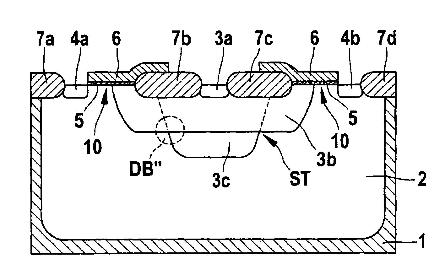
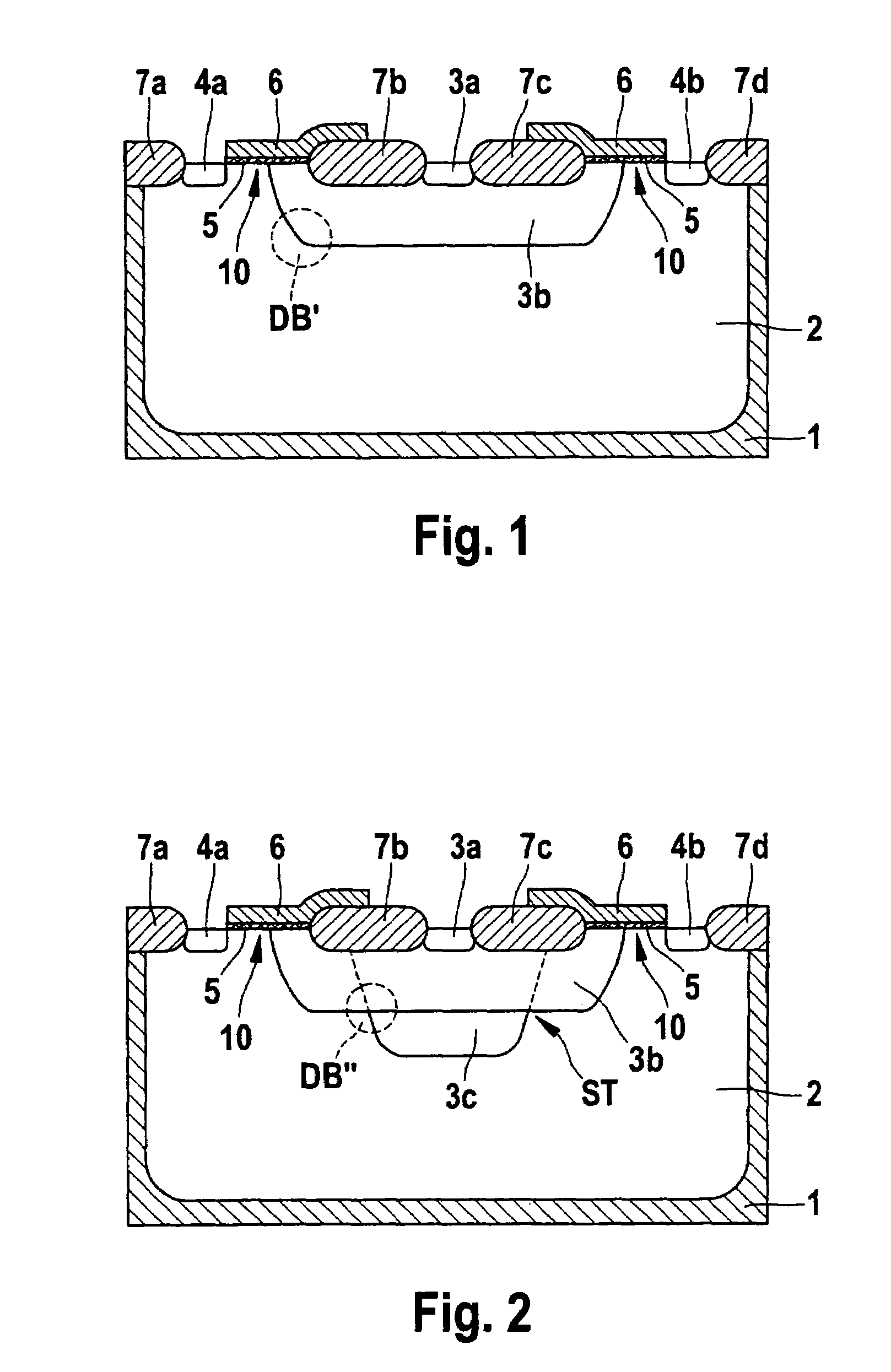
[0023]FIG. 1 shows a high-voltage MOS transistor according to a first specific embodiment of the present invention.

[0024]The high-voltage MOS transistor according to the first specific embodiment is a PMOS transistor integrated into a silicon p-semiconductor substrate 1, in which a first well 2 of the n-conductivity type is provided.

[0025]A strip-shaped drain region 3a, 3b of the p-conductivity type is introduced into first well 2, the drain region having a p+-drain terminal region 3a and a p-drain expansion region 3b. Two strip-shaped source regions 4a, 4b of the p+-conductivity type are introduced into first well 2 so as to be symmetric with respect to drain region 3a, 3b.

[0026]In each instance, a channel region 10 runs on the upper side of first well 2 between source region 4a or 4b and drain-extension region 3b. Field-oxide regions are designated by reference numerals 7a-d. Field-oxide regions 7b and 7c are situated on the upper side, in drain-extension region 3b, between drain...


PUM


Abstract

A high-voltage MOS transistor having: a first region of a first conductivity type; a source region of the second conductivity type, which is introduced into the first region; a drain region of the second conductivity type, which is introduced into the first region; a channel region on the upper side of the first region, between the source region and the drain region; a field-oxide region in the drain region, between the source region and the drain region; a gate-oxide region over the channel region and between the edge of the drain region and the field-oxide region; a magnetoresistor region between the source region and the drain region, over the gate-oxide region and over at least a part of the field-oxide region; the drain region having a drain-terminal region and a drain-extension region and the doping profile of the drain-extension region is designed so that an avalanche breakdown occurs between the source region and the drain region, in a breakdown region that is on the edge of the drain-extension region and is not situated at the upper surface. Also it describes corresponding manufacturing methods.

Description

FIELD OF THE INVENTION[0001]The present invention relates to a high-voltage MOS transistor. The present invention also relates to a corresponding manufacturing method.BACKGROUND INFORMATION[0002]Although applicable to any high-voltage MOS transistor, the present invention and the problem forming the basis of it are explained with regard to high-voltage MOS transistors in CMOS technology, which are manufactured according to the SVX technique (Smart Voltage Extension).[0003]High-voltage NMOS transistors and high-voltage PMOS transistors, which are manufactured in accordance with SVX technology, are known from IEEE Electron Device Letters, Vol. 21, No. 1, January, 2000, pages 40 to 42, C. Bassin, H. Ballan, and M. Declercq, “High-Voltage Device for 0.5-μm Standard CMOS Technology.” FIG. 4 shows a high-voltage PMOS transistor known from this printed publication.[0004]In FIG. 5, reference numeral 10 denotes a p-doped silicon semiconductor substrate. A deep n-well introduced into semicond...

Claims


Application Information

Patent Timeline
Patent Type & Authority Patents(United States)
IPC IPC(8): H01L29/94
CPCH01L29/66659H01L29/7835H01L29/0626H01L29/0847H01L29/42368
Inventor PETZOLD, KLAUSLINDENKREUZ, STEFFISTRAUSS, JOACHIM
Owner ROBERT BOSCH GMBH
Why Eureka
Try Eureka