
Image processor with noise reduction circuit

a noise reduction and image processor technology, applied in the field of digital imaging systems, can solve the problems of reducing the noise of one component, reducing the noise of the other components of the imaging system, and producing too much data, so as to achieve the effect of eliminating random noise such as readout noise and reducing nois

Active Publication Date: 2007-09-04
PIXIM
View PDF2 Cites 77 Cited by
  • Summary
  • Abstract
  • Description
  • Claims
  • Application Information

AI Technical Summary

Benefits of technology

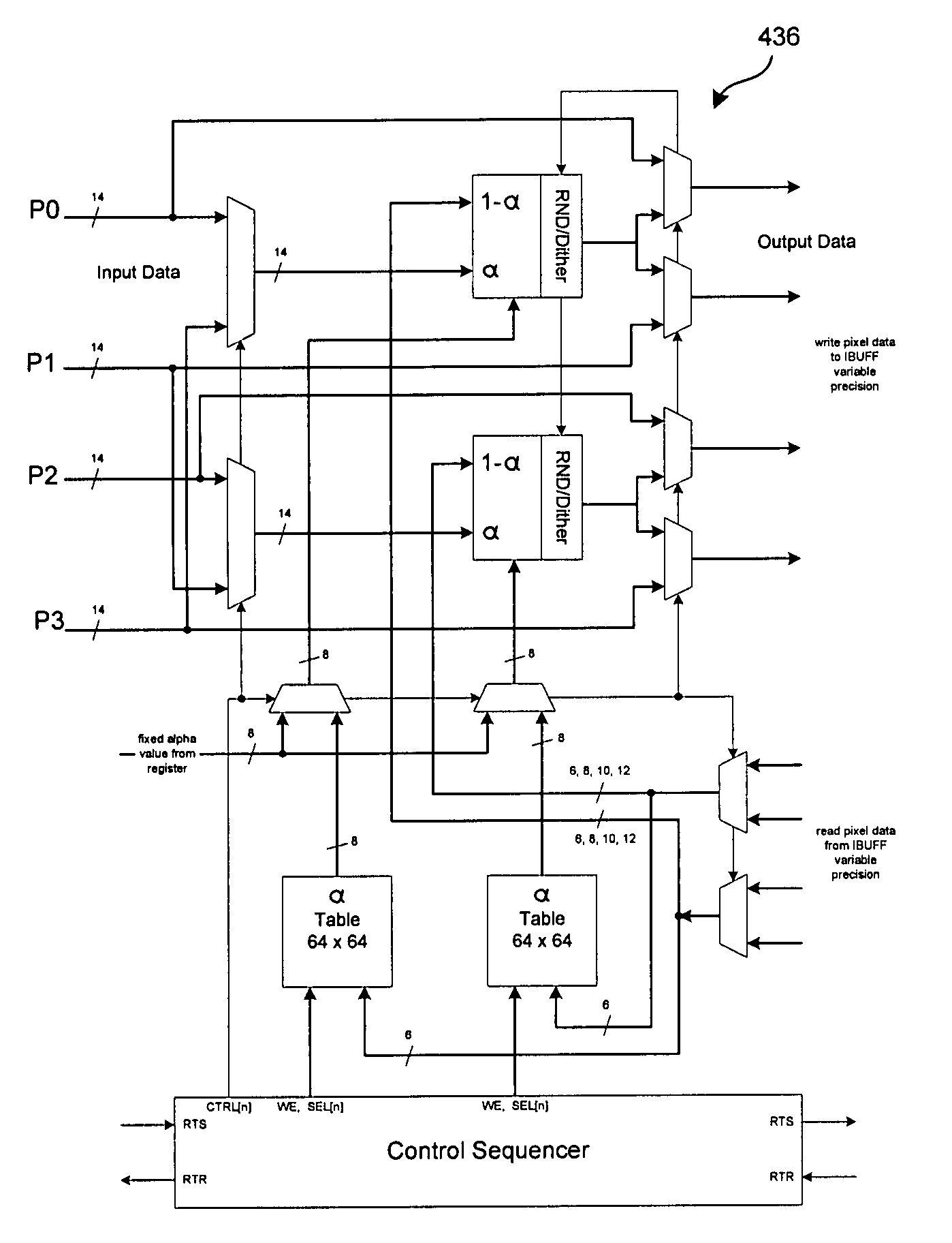
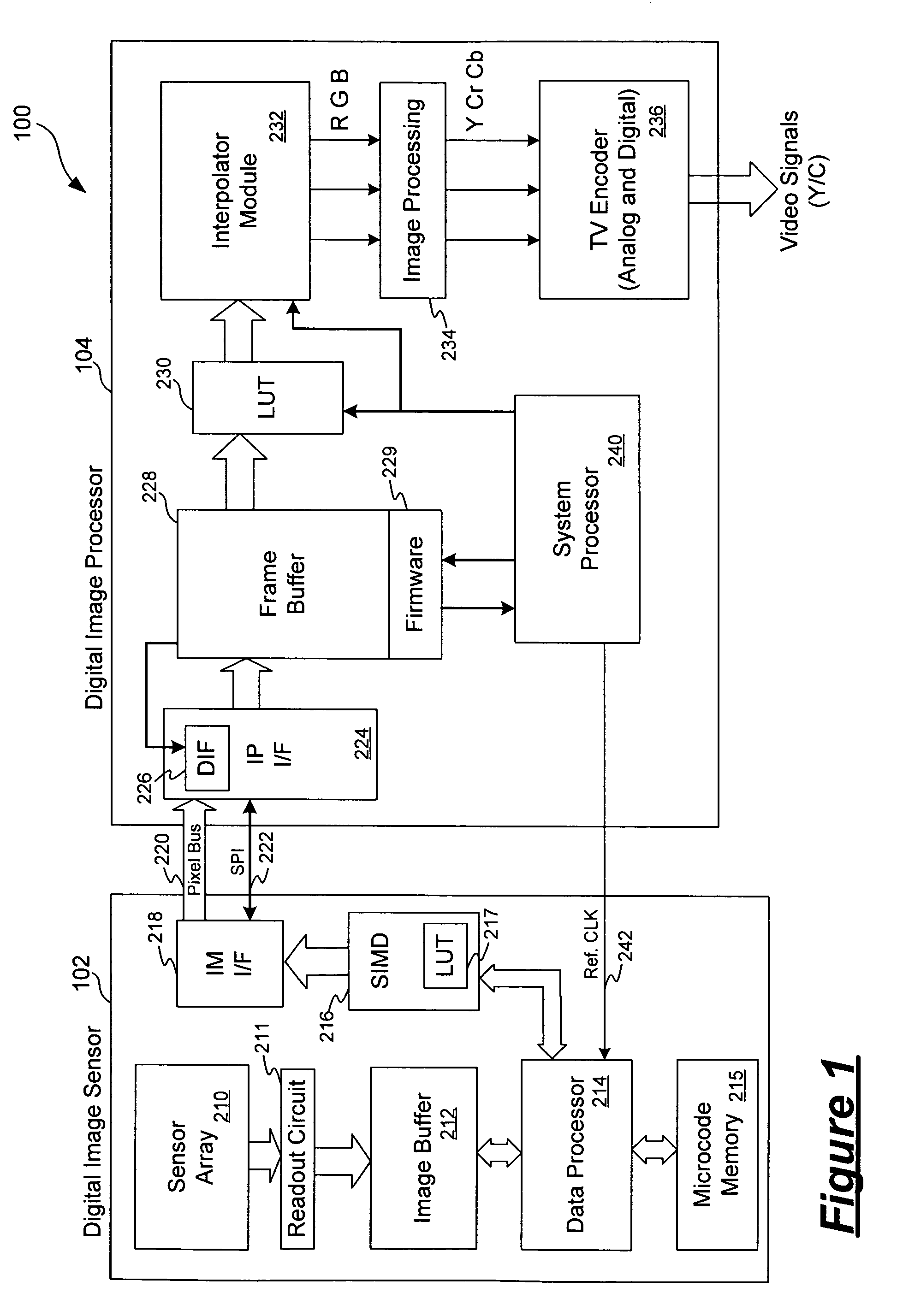
[0017]According to another aspect of the present invention, a digital imaging system includes an image sensor, an interface circuit, a frame buffer and an image processor. The image sensor includes a two-dimensional array of pixel elements where the image sensor outputs digital signals on a pixel bus as pixel data representing an image of a scene. The interface circuit is coupled to receive the pixel data from the pixel bus. The frame buffer is in communication with the interface circuit and is coupled to store pixel data provided by the interface circuit. Finally, the image processor operates to process the pixel data stored in the frame buffer to generate image data for displaying the image of the scene. In particular, the interface circuit includes a noise reduction circuit operated to perform signal processing on the pixel data received on the pixel bus for noise reduction. In this manner, random noise such as readout noise can be eliminated as pixel data are being transferred from the image sensor and stored in the frame buffer.

Problems solved by technology

While this ADC approach requires fairly simple and robust circuits, it has the disadvantages of producing too much data and suffering from poor low light performance.
As a result of using separate integrated circuits, noise generated in one component does not coupled easily to other components of the imaging system.
This is because noise coupling generally occurs through the power supply lines within an integrated circuit or through the substrate on which the integrated circuit is built.
As the components are separate, noise generated in one integrated circuit does not couple easily to another integrated circuit.
However, there are obstacles in developing a fully integrated SOC image sensor.
For example, CMOS image sensors typically suffer from temperature dependent dark current that reduces the signal to noise ratio of the image sensor and limits the sensitivity of the imaging system.
However, signal processing circuits typically consume a significant amount of power.
Therefore, dark current can be a particular problem in an SOC image sensor where large amount of image processing circuitry are incorporated with the image sensor.
However, the complexity of the image processing circuitry often requires at least 6 metal layers to implement to achieve the desired level of cost efficiency and signal and power distribution.
Thus, it is difficult and sometimes prohibitive to integrate an image sensor with complex processing circuitry.
Other obstacles exist in providing a SOC image sensor.

Method used


Image

  • Image processor with noise reduction circuit
  • Image processor with noise reduction circuit
  • Image processor with noise reduction circuit

Examples


Embodiment Construction

[0035]In accordance with the principles of the present invention, a video imaging system includes a digital image sensor and a digital image processor. The digital image sensor is implemented as a digital pixel sensor for providing high quality images with enhanced dynamic range. The digital image processor implements signal processing functions, such as for generating video images in a number of video formats and for providing image enhancement functions. The video imaging system also incorporates various noise reduction and image enhancement techniques for ensuring high quality video image output. Specifically, the video imaging system includes a noise reduction circuit for reducing random additive noise, such as readout noise, and enhancing video image quality at low light conditions. The video imaging system also implements a tone correction technique using blending masks and an algorithm for subtracting fixed pattern noise.

[0036]In one application, the video imaging system of t...


PUM


Abstract

A digital imaging system includes an image sensor, an interface circuit, a frame buffer and an image processor. The image sensor includes a two-dimensional array of pixel elements and outputs digital signals on a pixel bus as pixel data representing an image of a scene. The interface circuit is coupled to receive the pixel data from the pixel bus. The frame buffer is coupled to store pixel data provided by the interface circuit. The image processor operates to process the pixel data stored in the frame buffer to generate image data for displaying the image of the scene. The interface circuit includes a noise reduction circuit operated to perform signal processing on the pixel data received on the pixel bus for noise reduction. Thus, random noise such as readout noise can be eliminated as pixel data are being transferred from the image sensor and stored in the frame buffer.

Description

CROSS REFERENCE TO RELATED APPLICATION[0001]This application claims the benefit of U.S. Provisional Patent Application Ser. No. 60 / 404,803, filed Aug. 19, 2002, entitled “Image Processor Systems with Noise Reduction Circuit,” of Michael Frank, which application is incorporated herein by reference in its entirety.[0002]This application is related to the following concurrently filed and commonly assigned U.S. patent applications: U.S. patent application Ser. No. 10 / 634,302, entitled “Video Imaging System Including A Digital Image Sensor and A Digital Signal Processor,” of Michael Frank et al.; and U.S. patent application Ser. No. 10 / 634,296, entitled “Tone Correction Method Using A Blending Mask,” of Michael Frank et al. The aforementioned patent applications are incorporated herein by reference in their entireties.FIELD OF THE INVENTION[0003]The invention relates to digital imaging system and, in particular, to a digital imaging system including nose reduction circuits.DESCRIPTION OF...

Claims


Application Information

Patent Timeline
IPC IPC(8): H04N5/217H04N5/228H04N5/359H04N5/361H04N5/363H04N5/367H04N5/374
CPCH04N5/2351H04N5/2355H04N5/357H04N5/3575H04N5/37455H04N5/361H04N5/363H04N5/3651H04N5/367H04N23/71H04N23/741H04N25/616H04N25/65H04N25/671H04N25/60H04N25/68H04N25/63H04N25/772H04N25/76
Inventor FRANK, MICHAEL
Owner PIXIM
Learn More