Variable focal length lens comprising micromirrors

a variable focal length and mirror technology, applied in the direction of mirrors, instruments, mountings, etc., can solve the problems of complex driving mechanisms to control the relative positions of refractive lenses, slow response time, and low focusing efficiency, so as to facilitate the obtaining a large numerical aperture with a small rotation of the mirror, reduce the electrical resistance of the wire, and reduce the effect of electrical resistan

Active Publication Date: 2007-09-11
STEREO DISPLAY
View PDF13 Cites 22 Cited by
  • Summary
  • Abstract
  • Description
  • Claims
  • Application Information

AI Technical Summary

Benefits of technology

[0009]The micromirror array lens can be formed by a polar array of the micromirrors. For the polar array, each micromirror has a fan shape to increase an effective reflective area, so that the optical efficiency increases. The optical efficiency of the micromirror array lens can be improved by locating a mechanical structure upholding micromirrors and the actuating components under micromirrors to increase an effective reflective area. Electric circuits to operate the micromirrors can be replaced with known semiconductor microelectronics technologies such as MOS and CMOS. Applying the microelectronics circuits under micromirror array, the effective reflective area can be increased by removing necessary area for electrode pads and wires.
[0012]The lens can correct aberration, which is caused by optical effects due to the medium between the object and its image or is caused by defects of a lens system that cause its image to deviate from the rules of paraxial imagery, by controlling each micromirror independently. Independent control of each micromirror is also possible by replacing electric circuits required for control with known MOS or CMOS technologies and fabricating the circuits underneath the micromirrors using known microfabrication methods.
[0015]Furthermore, the micromirrors can be arranged in a curved plane with a predetermined curvature instead of in a flat plane, in order to facilitate obtaining a large numerical aperture with a small rotation of the mirrors.
[0016]In an improvement, the electrode wire can be made of material with a high electrical conductivity, preferably metal, to reduce the electrical resistance of the wire.
[0017]The advantages of the present invention are: (1) the micromirror array lens has a very fast response time because each micromirror has a tiny mass; (2) the lens has a large focal length variation because a large numerical aperture variation can be achieved by increasing the maximum rotational angle of the micromirror; (3) the lens has a high optical focusing efficiency; (4) the lens can have a large size aperture without losing optical performance. Because the micromirror array lens consists of discrete micromirrors, the increase in the lens size does not cause the increase in aberration caused by shape error of a lens; (5) the lens has a low cost because of the advantages of its mass productivity; (6) the lens can correct aberration; (7) the lens makes the focusing system much simple; (8) the lens can have arbitrary shape and / or size.

Problems solved by technology

It has complex driving mechanisms to control the relative positions of refractive lenses and a slow response time.
Unfortunately, it has a slow response time typically on the order of hundreds of milliseconds.
Even though the fastest response liquid crystal lens has the response time of tens of milliseconds, it has small focal length variation and low focusing efficiency.

Method used


Image

  • Variable focal length lens comprising micromirrors
  • Variable focal length lens comprising micromirrors
  • Variable focal length lens comprising micromirrors

Examples


first embodiment

[0052]A first embodiment is shown in FIGS. 1 through 7.

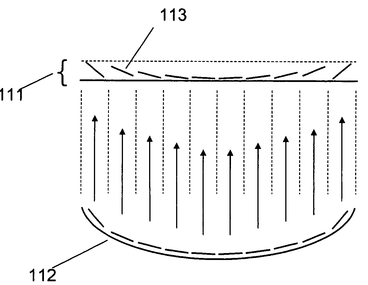
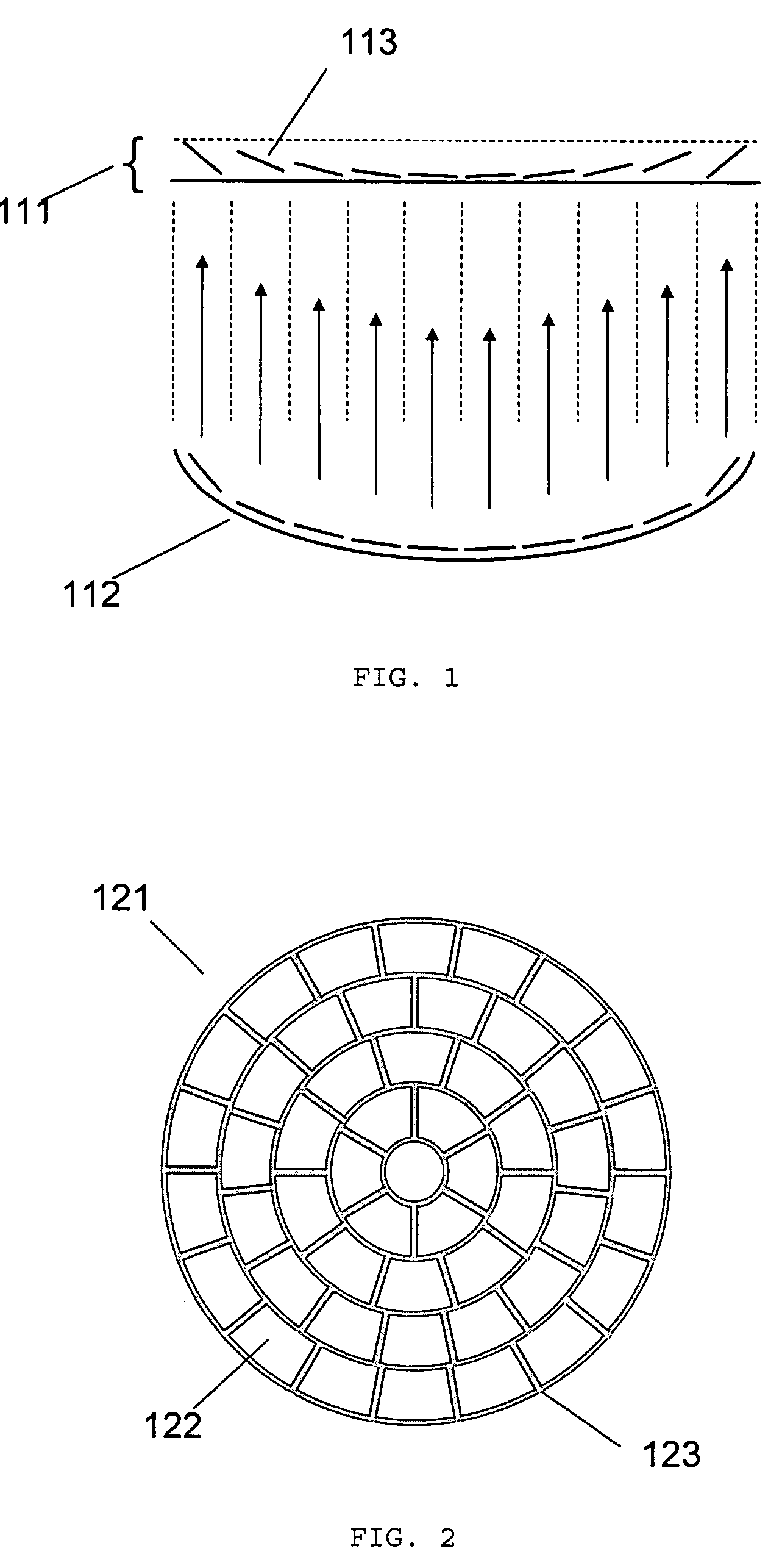
[0053]FIG. 1 illustrates the principle of the micromirror array lens 111. There are two conditions to make a perfect lens. The first is the converging condition that all lights scattered by one point of an object should converge into one point of the image plane. The second is the same phase condition that all converging light should have the same phase at the image plane. To satisfy the perfect lens conditions, the surface shape of conventional reflective lens 112 is formed to have all lights scattered by one point of an objective to be converged into one point of the image plane and have the optical path length of all converging light to be same.

[0054]A micromirror array arranged in flat plane can satisfy two conditions to be a lens. Each of the micromirrors 113 rotates to converge the scattered light. Because all micromirrors 113 of the micromirror array lens 111 are arranged in a flat plane as shown in FIG. 1, the optical pa...

second embodiment

[0069]A second embodiment, variable focal length lens comprising micromirrors with one degree of freedom rotation, is shown in FIGS. 8 through 11.

[0070]FIG. 8 illustrates the principle of the conventional micromirror array lens 211, which corresponds to FIG. 1 of the first embodiment in its description.

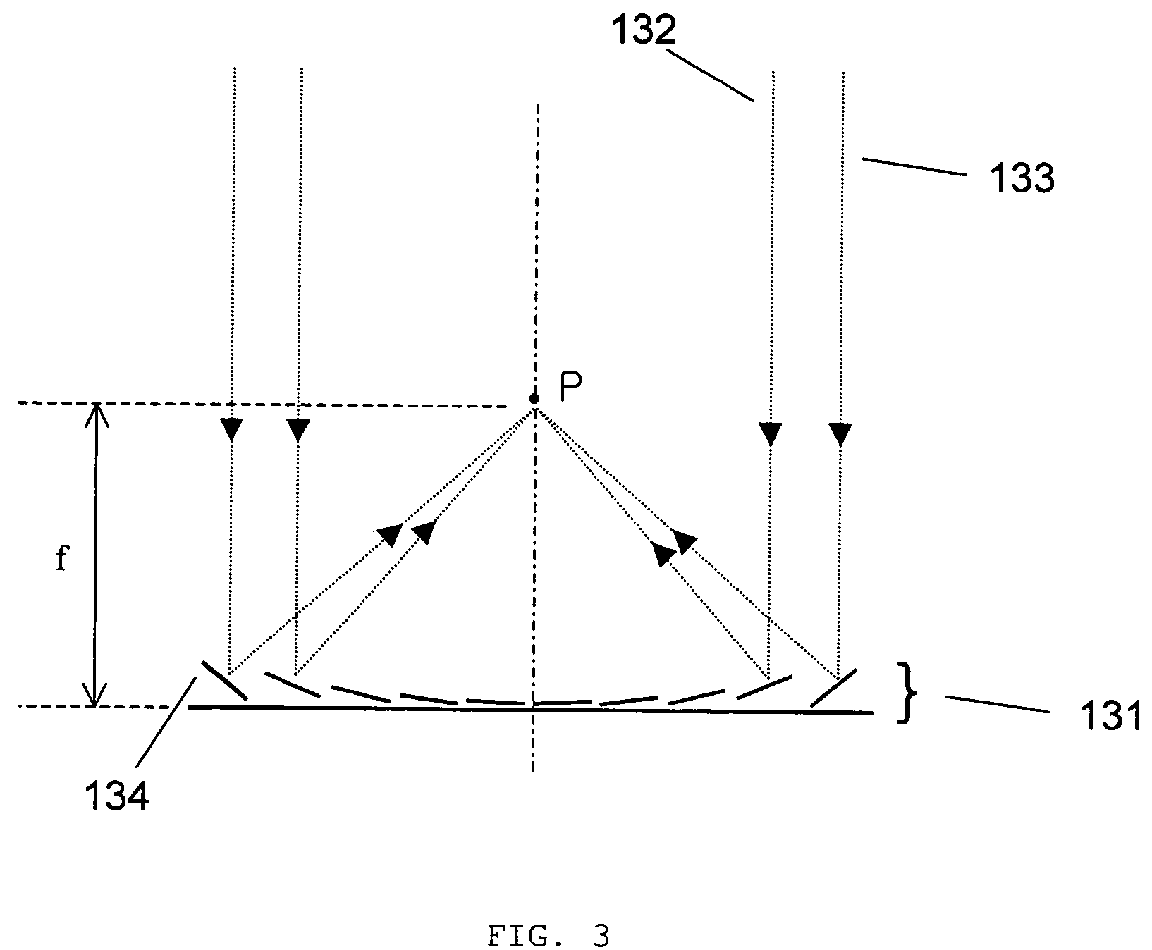
[0071]FIG. 9 illustrates how the micromirror array lens 221 comprising micromirrors with one DOF rotation images. Arbitrary scattered lights 222, 223 are converged into one point P of the image plane by controlling the positions of the micromirrors 224. The phases of arbitrary lights 222, 223 are not adjusted to satisfy same phase condition. Even though the phase condition is not satisfied, low quality imaging or focusing is still possible.

[0072]FIG. 10 illustrates the in-plane view of a circular micromirror array lens 231 comprising micromirrors with one DOF rotation. All micromirrors are arranged in a flat plane because they are fabricated by known microfabrication processes.

[0073]I...

third embodiment

[0075]A third embodiment, variable focal length lens comprising micromirrors with two degrees of freedom rotation, is shown in FIGS. 12 through 18.

[0076]FIG. 12 illustrates the principle of a conventional micromirror array lens 311, which corresponds to FIG. 1 of the first embodiment in its description.

[0077]FIG. 13 illustrates how the micromirror array lens 321 comprising micromirrors with two DOF rotation images. Arbitrary scattered lights 322, 323 are converged into one point P of the image plane by controlling the positions of the micromirrors 324. The phases of arbitrary light 322, 323 are not adjusted to satisfy the same phase condition. Even though the phase condition is not satisfied, low quality imaging or focusing is still possible.

[0078]It is desired that each of the micromirrors 324 has a curvature because the ideal shape of a conventional reflective lens 312 has a curvature. According to focal length change of the lens, the curvature of micromirror should be controlled....


PUM

PropertyMeasurementUnit
focal lengthaaaaaaaaaa
degree of freedomaaaaaaaaaa
electrical conductivityaaaaaaaaaa

Abstract

A variable focal length lens consists of many micromirrors with degrees of freedom rotation and / or degrees of freedom translation and actuating components. As operating methods for the lens, the actuating components control the positions of micromirrors electrostatically and / or electromagnetically. The optical efficiency of the variable focal length lens is increased by locating a mechanical structure upholding micromirrors and the actuating components under micromirrors. The lens can correct aberration by controlling each micromirror independently. The lens can also be of a desired arbitrary shape and / or size. The micromirrors are arranged in a flat plane or in a curved plane with a predetermined curvature. The electrodes determining the position of the micromirrors can be made of material with high electrical conductivity, preferably metal. The surface material of the micromirror is made of a material with high reflectivity such as aluminum, silver, and gold, which are coated with multi-layer dielectric material or antioxidant.

Description

RELATED APPLICATION[0001]This application is a continuation-in-part of U.S. patent application Ser. Nos. 10 / 855,554 for “Variable Focusing Lens comprising Micromirrors with One Degree of Freedom Rotation” filed on May 27, 2004 now U.S. Pat. No. 6,970,284, Ser. No. 10 / 855,715 for “Variable Focusing Lens comprising Micromirrors with Two Degrees of Freedom Rotation” filed on May 27, 2004 now U.S. Pat. No. 7,031,046, Ser. No. 10 / 855,287 for “Variable Focusing Lens comprising Micromirrors with Two Degrees of Freedom Rotation and One Degree of Freedom Translation” filed on May 27, 2004 now U.S. Pat. No. 6,934,072, Ser. No. 10 / 857,796 for “Variable Focusing Lens comprising Micromirrors with One Degree of Freedom Rotation and One Degree of Freedom Translation” filed on May 28, 2004 now U.S. Pat. No. 6,934,073, Ser. No. 10 / 857,714 for “Array of Micromirror Array Lenses” filed on May 28, 2004 now U.S. Pat. No. 7,161,729, Ser. No. 10 / 857,280 for “Variable Focusing Lens comprising Micromirrors ...

Claims


Application Information

Patent Timeline
Patent Type & Authority Patents(United States)
IPC IPC(8): G02B7/182G02B26/00G02B7/32G02B26/08G02B26/10G02B27/40G02F1/29
CPCG02B3/00G02B7/32G02B17/0694G02B26/0833G02B26/0841G02B26/085G02B26/105G02B27/0068G02B27/40
Inventor KIM, TAE HYEONBAEK, SANG HYUNE
Owner STEREO DISPLAY
Why Eureka
Try Eureka