Angiographic injector system with multiple processor redundancy
What is Al technical title?
Al technical title is built by PatSnap Al team. It summarizes the technical point description of the patent document.
a technology of injector system and multiple processor, applied in the field of angiography, can solve the problems of toxic effects, inability to accommodate any safety features in manual systems, and suboptimal quality of angiographic studies, and achieve the effects of avoiding operator errors, being convenient to use, and being convenient to us
Inactive Publication Date: 2007-09-11
ACIST MEDICAL SYST
View PDF66 Cites 61 Cited by
Summary
Abstract
Description
Claims
Application Information
AI Technical Summary
This helps you quickly interpret patents by identifying the three key elements:
Problems solved by technology
Method used
Benefits of technology
[0013]This invention provides an automated angiographic injection system that is extremely flexible and user friendly and which provides real-time instantaneous injection parameter information to the operator. The system features a liquid crystal display screen that displays a sequence of start-up instructions to the operator without requiring additional manuals or hard copy instructions during such procedures. User communication with the system's microprocessor(s) is readily and accurately permitted through touch-responsive pads on the visual display. Since the system microprocessor(s) always includes the most updated
Problems solved by technology
Such manual systems typically do not accommodate any safety features such as the restriction or prevention of injections outside of predetermined injection parameters (such as rate or pressure), and generally do not include active sensors or alarms to detect air bubbles or other hazards.
Since the optimal flow rate can vary considerably between patients, the lack of ability of such prior art systems to vary the rate of injection during an injection procedure can result in suboptimal quality of angiographic studies.
Consequently, the initially selected volume or flow rate parameters for an injection of contrast material may be insufficient to outline a desired structure on an X-ray image, thereby necessitating another injection.
Conversely, an excessive flow rate may injure the cardiovascular vessel being injected, cause the catheter to be displaced relative to the patent or lead to toxic effects (such as abnormal heart rhythm) from contrast material overdose.
While the prior automated systems have significantly improved the accuracy and reliability of angiography injection procedures, the known systems have not been as user friendly as desired, have not had automated capability to determine default injection parameters unique to the physiology or other values of the patent to be tr
Method used
Image
Click on the blue label to locate the original text in one second.
Reading with bidirectional positioning of images and text.
Examples
Embodiment Construction
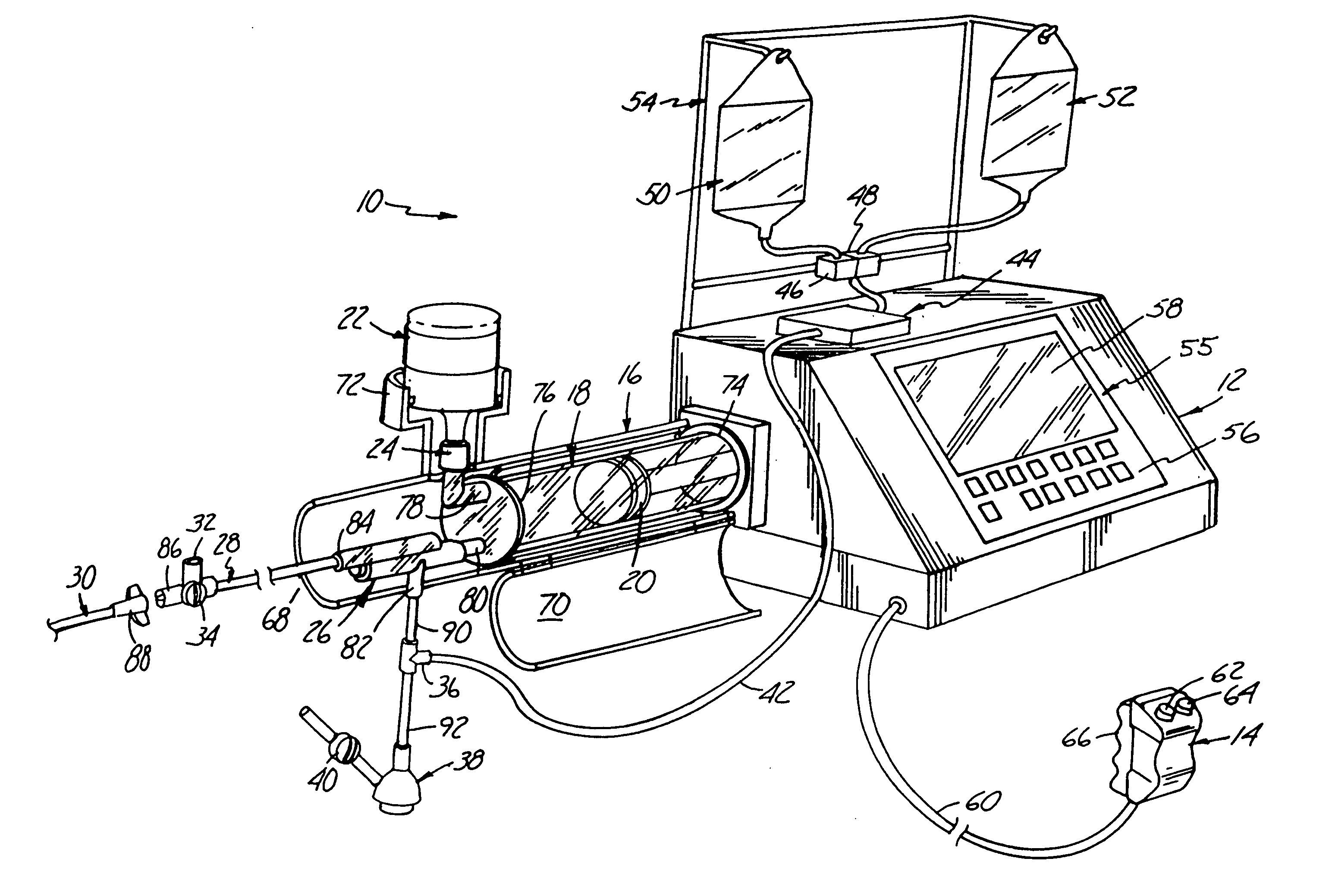
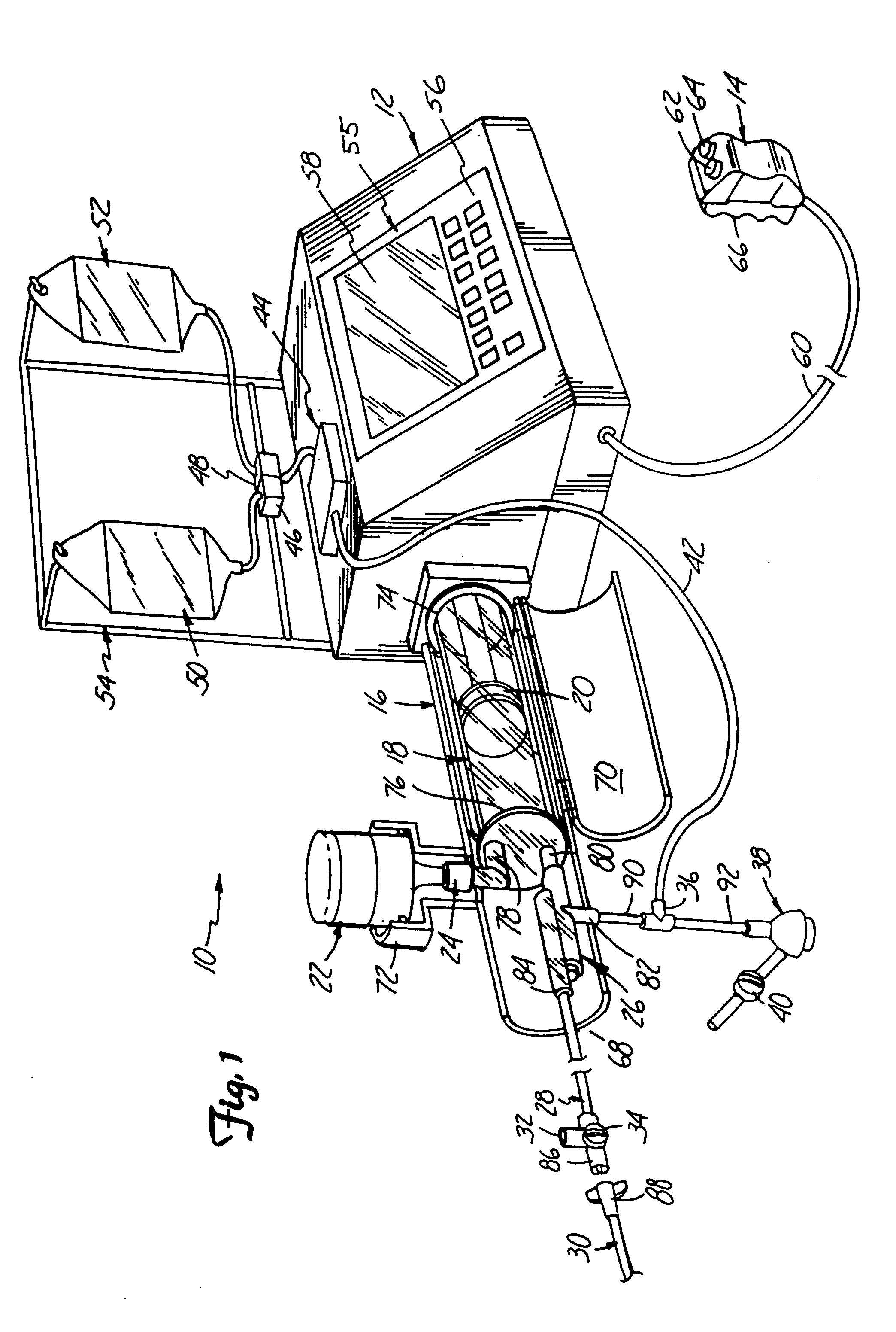
[0062]As will be appreciated upon a more detailed description herein, the principles of this invention can be applied to many different physical configurations of automated angiographic injector systems. An example of one such system, as described in more detail in U.S. patent application Ser. No. 08 / 426,149 referenced above and herein fully incorporated by reference, will be generally described below. It will be understood that while specific angiographic system(s) will be described with respect to preferred embodiments of the invention, the principles of this invention are not limited to use in the preferred embodiments described. Referring to the Drawings, FIG. 1 shows an angiographic injector system 10 for injecting radiographic contrast material into a blood vessel under interactive physician control. System 10 includes main console 12, hand held remote control 14, syringe holder 16, syringe body 18, syringe plunger 20, radiographic material reservoir (bottle) 22, one-way valve...
PUM
Abstract
An angiographic injector system and a method of controllably delivering medical fluid to a patient from an angiographic injector system are disclosed. A multiple processor control system is used to actively control the injection process and to monitor sensed functions of the system. The multiple processors provide dual redundancy safety circuits for critical control functions such as syringe motor drive speed and current. A motor/servo-amplifier nested control function is also disclosed. A unique method and apparatus are disclosed for establishing injection parameter default values just prior to an injection procedure that are based on physiological values of the patient to be treated. The injector system uses an interactive display panel that presents sequenced set-up screens to the user and which enables the user to select injection procedures, parameters and other modes of operation directly through the interactive panel.
Description
CROSS-REFERENCE TO RELATED APPLICATIONS[0001]This application is a continuation-in-part of U.S. patent application Ser. No. 08 / 957,801 filed on Oct. 24, 1997, pending entitled ANGIOGRAPHIC INJECTOR SYSTEM WITH AUTOMATIC HIGH / LOW PRESSURE SWITCHING which is a continuation-in-part of U.S. patent application Ser. No. 08 / 946,293, filed on Oct. 7, 1997, now U.S. Pat. No. 5,800,397 which is a file wrapper continuation application of U.S. patent application Ser. No. 08 / 426,148 filed on Apr. 20, 1995, now abandoned which are all herein incorporated by reference. This application also incorporates by reference the contents of the following U.S. patent applications: Ser. No. 08 / 957,228, entitled Dual Port Syringe, filed on Oct. 24, 1997; Ser. No. 08 / 965,583, entitled Pneumatic Controller and Method, filed on Nov. 6, 1997; and Design application Ser. No. 29 / 078,023; entitled Hand-Held Pneumatic Control Device, filed on Nov. 6, 1997; all three of which are owned by a common assignee of this app...
Claims
Application Information
Patent Timeline
Application Date:The date an application was filed.
Publication Date:The date a patent or application was officially published.
First Publication Date:The earliest publication date of a patent with the same application number.
Issue Date:Publication date of the patent grant document.
PCT Entry Date:The Entry date of PCT National Phase.
Estimated Expiry Date:The statutory expiry date of a patent right according to the Patent Law, and it is the longest term of protection that the patent right can achieve without the termination of the patent right due to other reasons(Term extension factor has been taken into account ).
Invalid Date:Actual expiry date is based on effective date or publication date of legal transaction data of invalid patent.