Phosphor and light source comprising such a phosphor

a technology of phosphor and light source, which is applied in the direction of discharge tube/lamp details, discharge tube luminescent screens, discharge tubes/lamp details, etc., can solve the problems of low efficiency of conversion, low excitability and consequently also the efficiency of conversion, and relatively unstable or rather inefficient, etc., to achieve low temperature quenching and without significant efficiency loss

Active Publication Date: 2007-09-11
RIKEN CO LTD +3
View PDF25 Cites 30 Cited by
  • Summary
  • Abstract
  • Description
  • Claims
  • Application Information

AI Technical Summary

Benefits of technology

[0004]It is an object of the present invention to provide a phosphor which is distinguished by being robust and highly sensitive in terms of the selection of color locus within a wide range of the chromaticity diagram.
[0005]A further object is to produce a highly efficient, stable green phosphor with a garnet structure for use in LEDs with full-color capability based on a primary LED which emits at a short wavelength, for example in the blue, with a long service life.
[0006]A further object is to produce a highly efficient garnet phosphor with an accurately matched color locus for photon excitation, in particular by white LEDs, and also to provide a light source, in particular a white LED with a neutral to warm white luminous color and with just one phosphor as converter. If a single phosphor is used, it is possible to restrict fluctuations in color locus and to simplify production, since there are no mixing and sedimentation problems. Of course, the phosphor can also be used together with other phosphors to provide a light source.

Problems solved by technology

However, phosphors of this type, if Y is not the main component of the lattice site occupied by rare earths, are relatively unstable or rather inefficient or have only a low absorption capacity.
Although Al may be partially replaced by Ga in the garnet, in particular with these known phosphors with a color locus in the green spectral region, the excitability and consequently also the efficiency of the conversion are not satisfactory.
A further restriction on the desired color locus of a known garnet phosphor aimed at realizing a white LED is that a relatively high cerium concentration tends to be required for this purpose, but this can only be realized with very considerable difficulty in terms of manufacturing technology.
This two-component system in principle has a number of drawbacks: the longer-wave phosphor generally absorbs the emission of the shorter-wave phosphor.
Finally, the known phosphors generally have different temperature dependencies, which can result in a color locus drift in the event of the LED being dimmed or at different ambient temperatures.

Method used


Image

  • Phosphor and light source comprising such a phosphor
  • Phosphor and light source comprising such a phosphor
  • Phosphor and light source comprising such a phosphor

Examples


Embodiment Construction

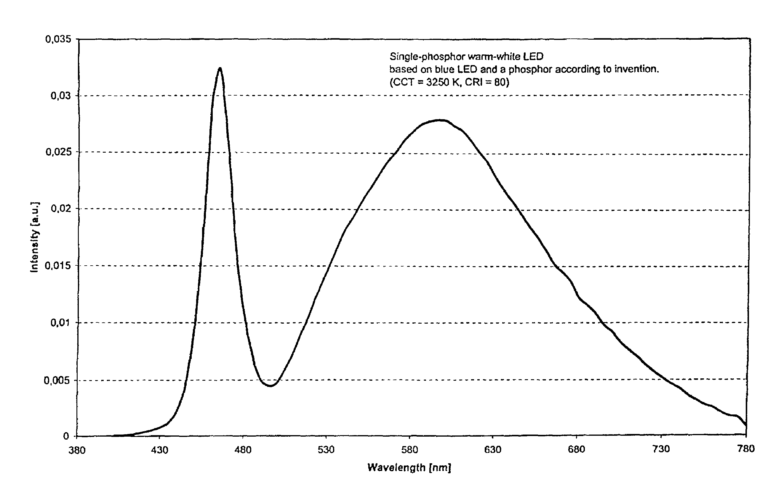
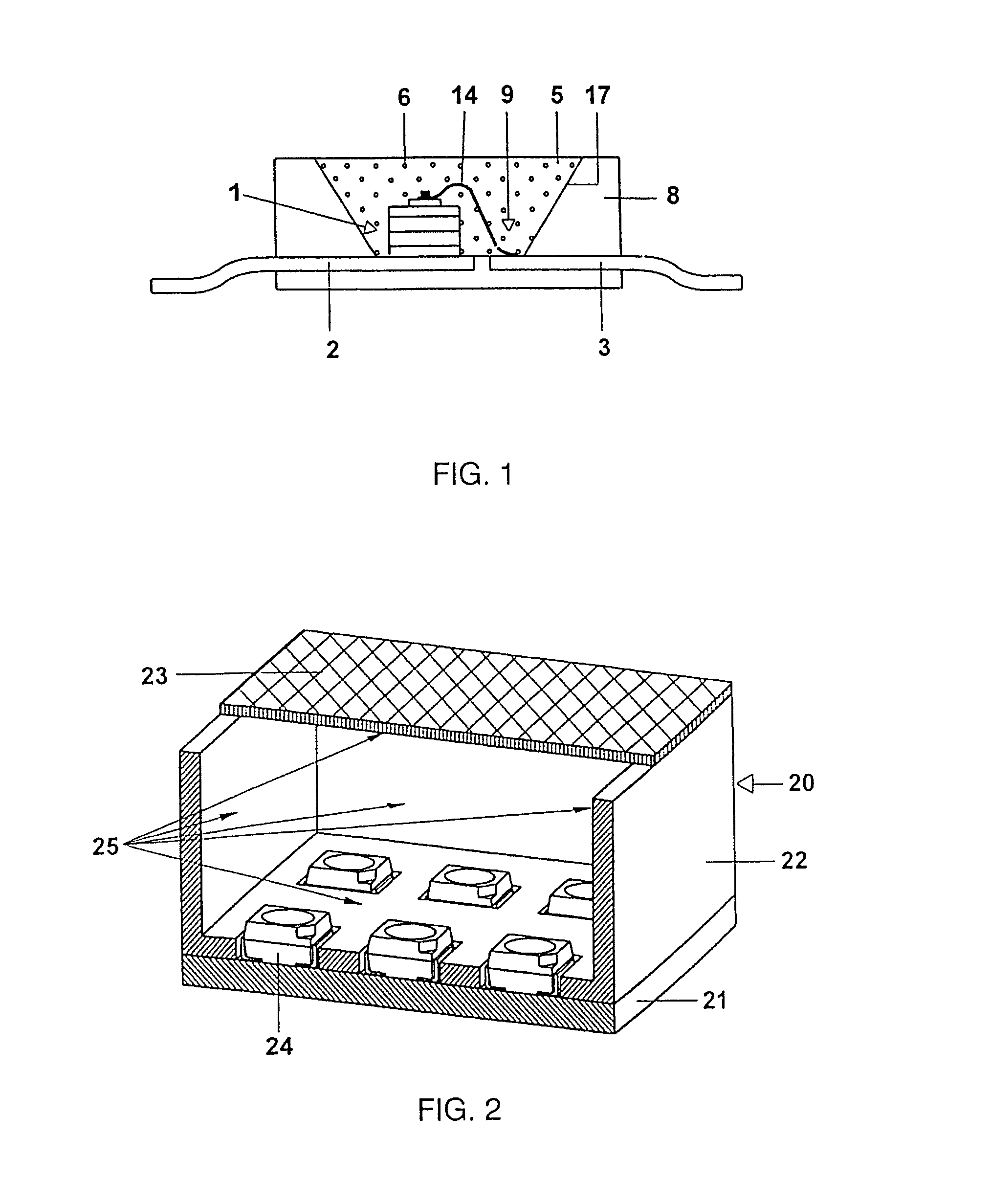
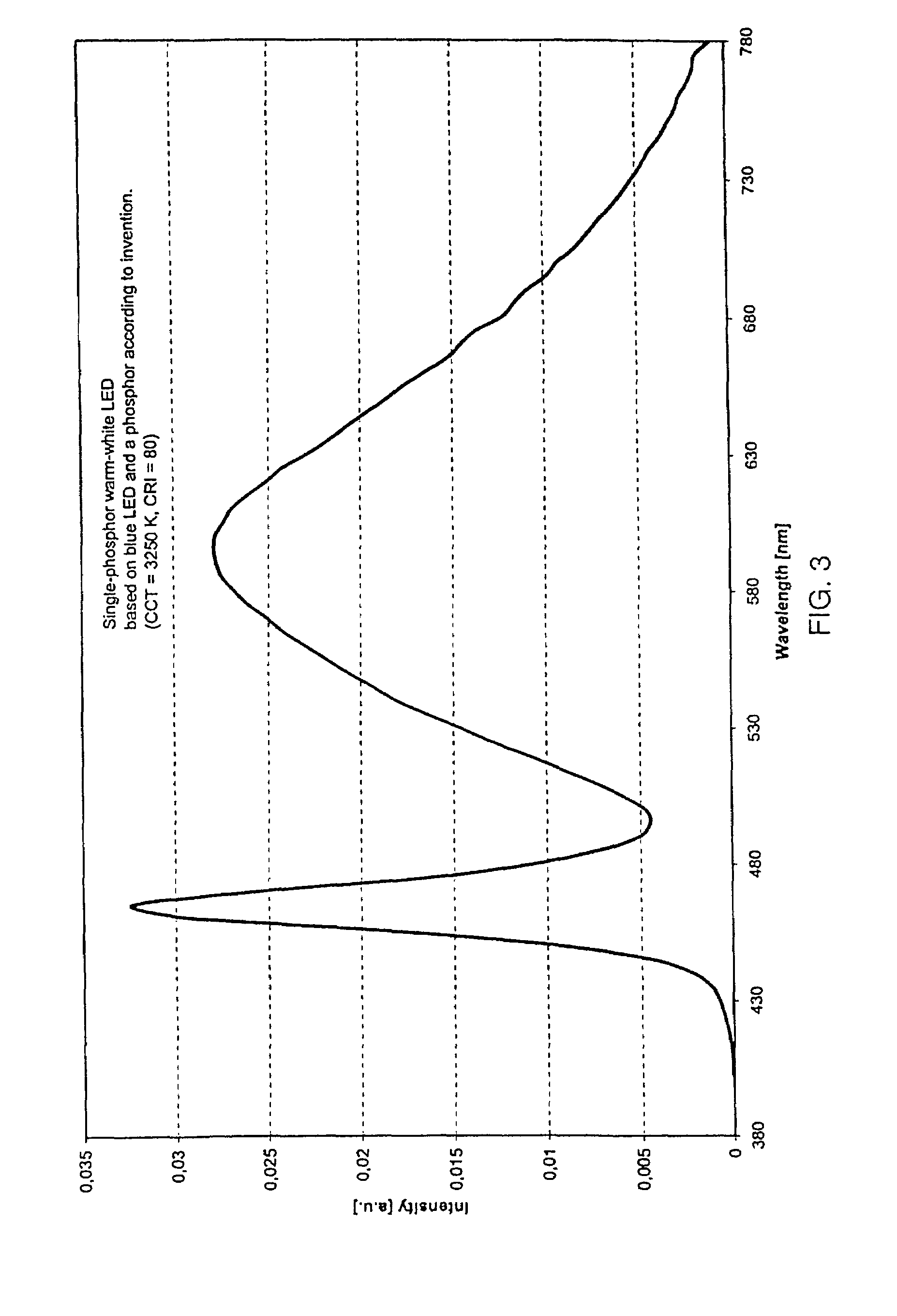
[0062]For use in a warm-white LED together with a GaInN chip, by way of example a similar structure to that described in U.S. Pat. No. 5,998,925 is used. The structure of a light source of this type for white light is specifically shown in FIG. 1. The light source is a semiconductor component (chip 1) of type InGaN with a peak emission wavelength of 460 nm and a first and second electrical connection 2, 3 embedded in an opaque basic housing 8 in the region of a recess 9. One of the connections 3 is connected to the chip 1 via a bonding wire 14. The recess has a wall 17 which serves as reflector for the primary radiation of the chip 1. The recess 9 is filled with a potting compound 5, which as its main constituents contains an epoxy casting resin (for example 80 to 90% by weight) and phosphor pigments 6 (for example less than 15% by weight). Further small fractions are attributable, inter alia, to Aerosil. The phosphor pigments consist of pigments of silicon-containing garnet. These ...


PUM

PropertyMeasurementUnit
dominant wavelengthaaaaaaaaaa
color temperatureaaaaaaaaaa
peak emission wavelengthaaaaaaaaaa

Abstract

A phosphor with a garnet structure is distinguished by the addition of Si. It is suitable in particular for photon excitation by light sources with an emission between 250 and 550 nm.

Description

TECHNICAL FIELD[0001]The invention is based on a phosphor and light source having such a phosphor. It relates in particular to a garnet-based phosphor which is suitable for use in light sources such as LEDs and lamps.PRIOR ART[0002]DE-U 201 08 013 has already disclosed a phosphor and light source comprising such a phosphor, in which a phosphor is a garnet of defined rare earths. The use of various rare earths provides the option of setting the color locus of the phosphor within certain limits. However, phosphors of this type, if Y is not the main component of the lattice site occupied by rare earths, are relatively unstable or rather inefficient or have only a low absorption capacity. Although Al may be partially replaced by Ga in the garnet, in particular with these known phosphors with a color locus in the green spectral region, the excitability and consequently also the efficiency of the conversion are not satisfactory. A further restriction on the desired color locus of a known ...

Claims


Application Information

Patent Timeline
Patent Type & Authority Patents(United States)
IPC IPC(8): C09K11/78C09K11/79C09K11/80C09K11/77H01L33/26H01L33/48H01L33/50
CPCC09K11/7769C09K11/7774H01L2224/48091H01L2224/73265H01L2224/48247H01L2224/32245H01L2924/00014H01L2924/00H01L2924/12044C09K11/77748H01L2924/00012C09K11/77C09K11/59
Inventor FIEDLER, TIMFRIES, TORSTENJERMANN, FRANKZACHAU, MARTINZWASCHKA, FRANZ
Owner RIKEN CO LTD
Why Eureka
Try Eureka