

Digital synchronizing generator
- Summary
- Abstract
- Description
- Claims
- Application Information
AI Technical Summary
Problems solved by technology
Method used
Image

Examples
Embodiment Construction
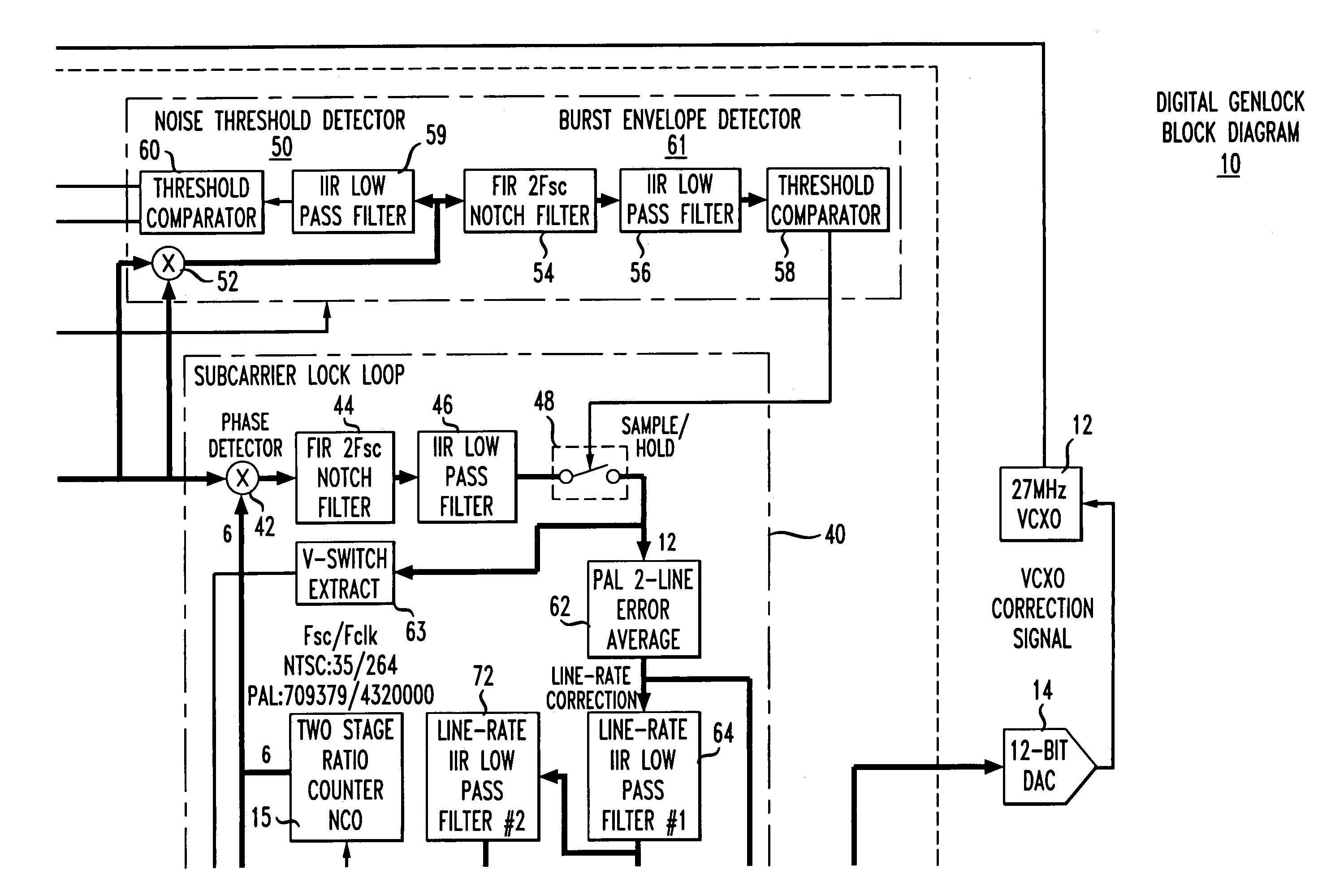
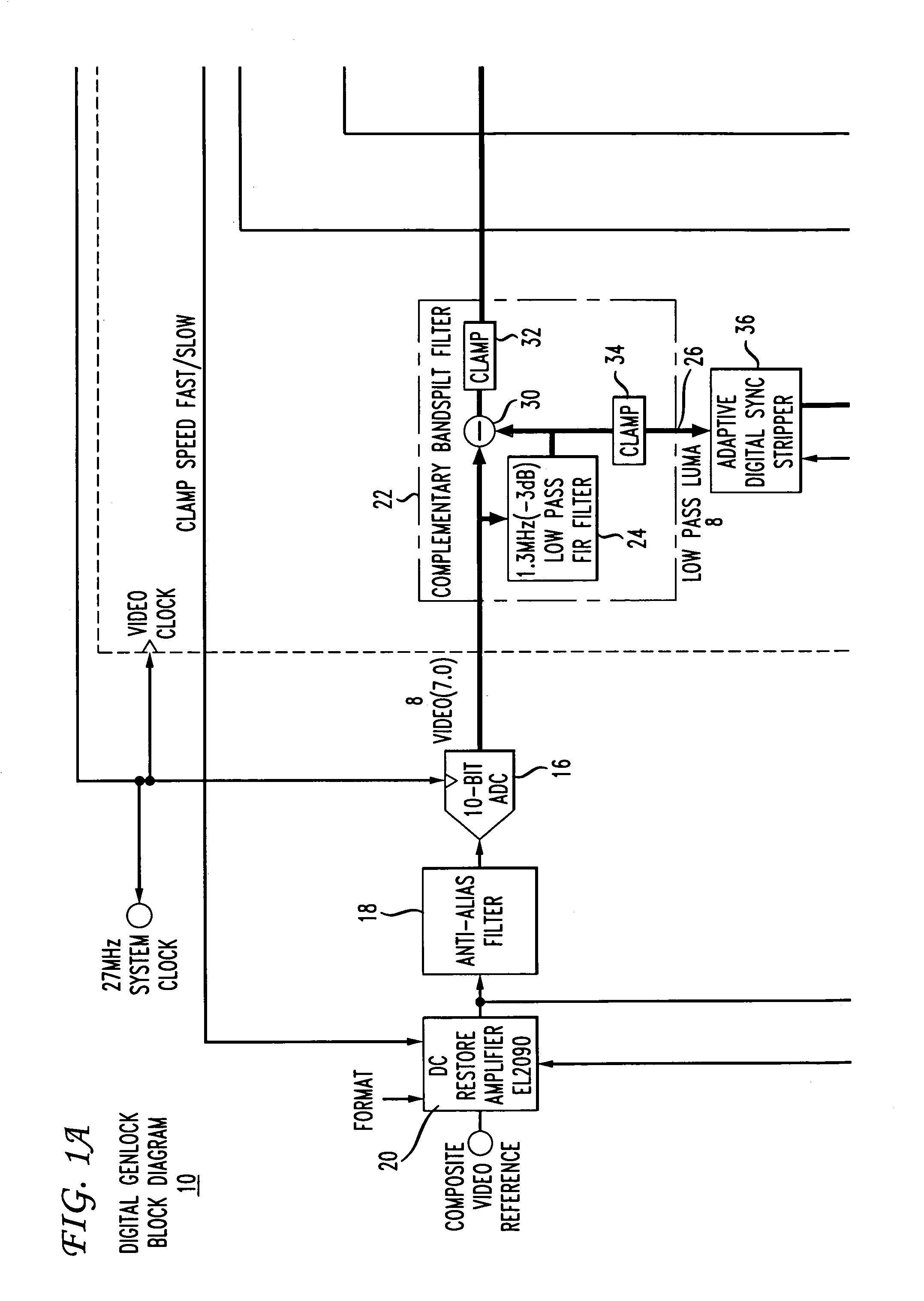
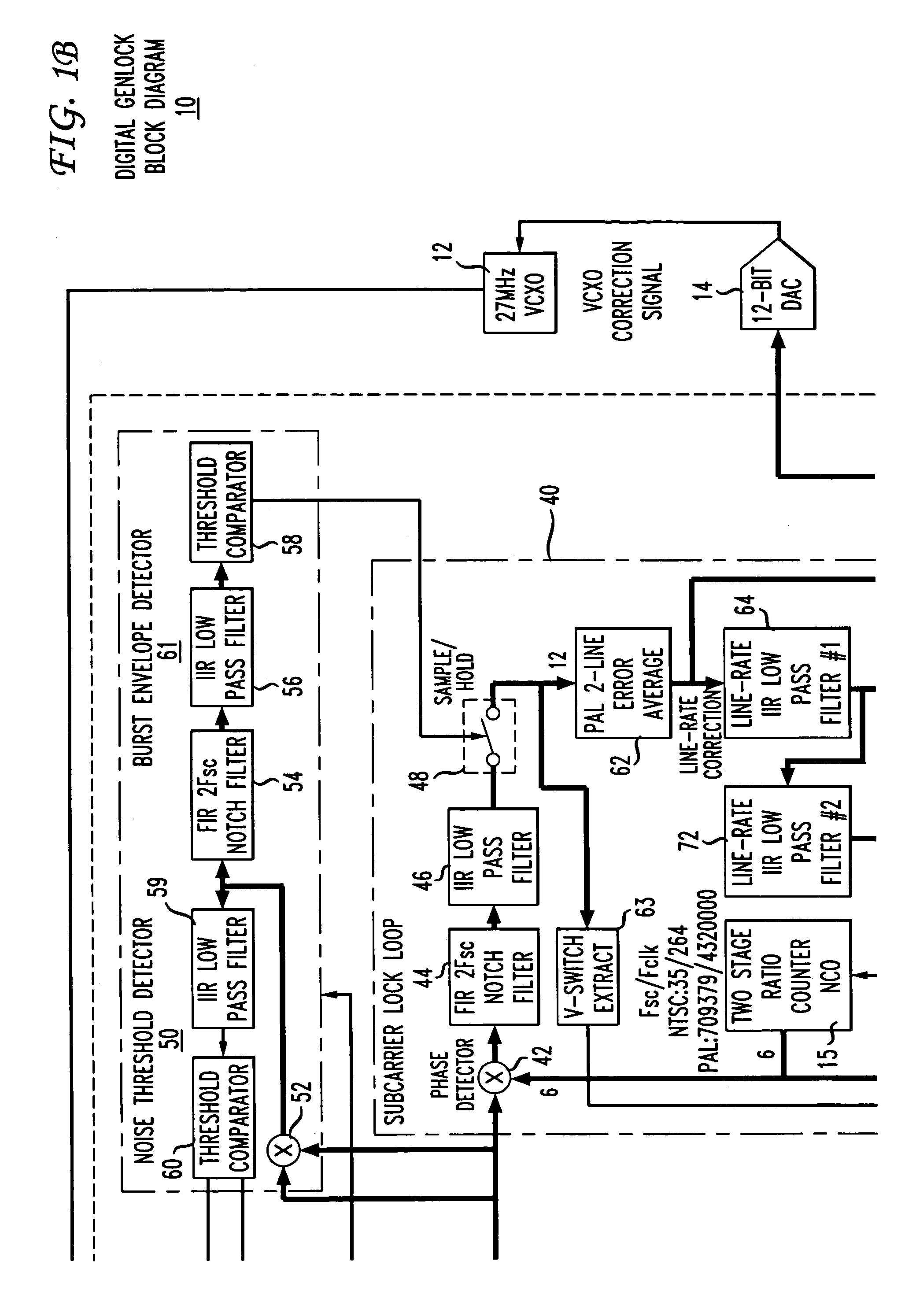
[0015]FIG. 1 depicts a block schematic diagram of an illustrative embodiment of a digital synchronizing generator 10 in accordance with the present principles. The generator 10 includes a Voltage Controlled Oscillator (VCXO) 12 that generates a clock frequency of 27 MHz for locking to an incoming video signal for synchronizing one or more video sources (not shown). The VCXO 12 responds to a VCXO correction signal generated by Burst Lock / Color framing circuit 13 and converted from a digital to an analog signal by a Digital-to-Analog Converter (DAC) 14 prior to receipt at the VCXO. As described below, the framing circuit 13 generates the VCXO correction signal in accordance with a static phase offset from an ideal 90° phase offset between the digitized burst component of the incoming video signal and a numerically controlled oscillator clock 15 described in greater detail below. In this way, the 27 MHz. clock signal becomes locked to the incoming video signal.
[0016]The 27 MHz. clock s...
PUM
 Abstract
Description
Claims
Application Information