Active polyphase filter

a polyphase filter and active technology, applied in the field of polyphase filters, can solve the problems of reducing the sensitivity of component variations in integrated circuits, adding cost and complexity to circuit designs, and reducing the number of energy losses, so as to simplify circuit designs, reduce costs, and similar gm properties

Active Publication Date: 2007-09-18
MEDIATEK INC
View PDF6 Cites 7 Cited by
  • Summary
  • Abstract
  • Description
  • Claims
  • Application Information

AI Technical Summary

Benefits of technology

[0012]In accordance with yet another aspect of the present invention, the first pair of load resistances and the second pair of load resistances are substantially equal. Having substantially equal load resistance simplifies fabrication of the circuit and optimizes operation of the polyphase filter.
[0015]In accordance with another aspect of the present invention, the transistors include bipolar junction devices having substantially similar gm properties. The transistors of the cascode differential amplifiers afford the polyphase filter to produce a gain at the outputs. Producing a gain at the outputs eliminates the requirement for buffer circuits in most cases that will simplify circuit designs and reduce costs.

Problems solved by technology

Consequently, extra buffers are often used at the outputs of the passive polyphase filters which add cost and complexity to a circuit design.
Moreover, as more stages are added, the energy loss is proportional to the number of stages added to the filter.
Moreover, feedback loops between the inputs and outputs of the active RC filter reduce sensitivity to component variations in integrated circuits.
However, a major drawback of operational amplifier based polyphase filters is the limited bandwidth which limit operation to low frequencies.
Concededly, circuit designers have been limited to using passive polyphase filter designs in high frequency applications.
Even though the passive polyphase filter designs heavily attenuate signals and require extra buffers with large gain, circuit designers have had little choice but to add the extra components to compensate for the signal loss of the passive polyphase filter designs.

Method used


Image

  • Active polyphase filter
  • Active polyphase filter
  • Active polyphase filter

Examples


Embodiment Construction

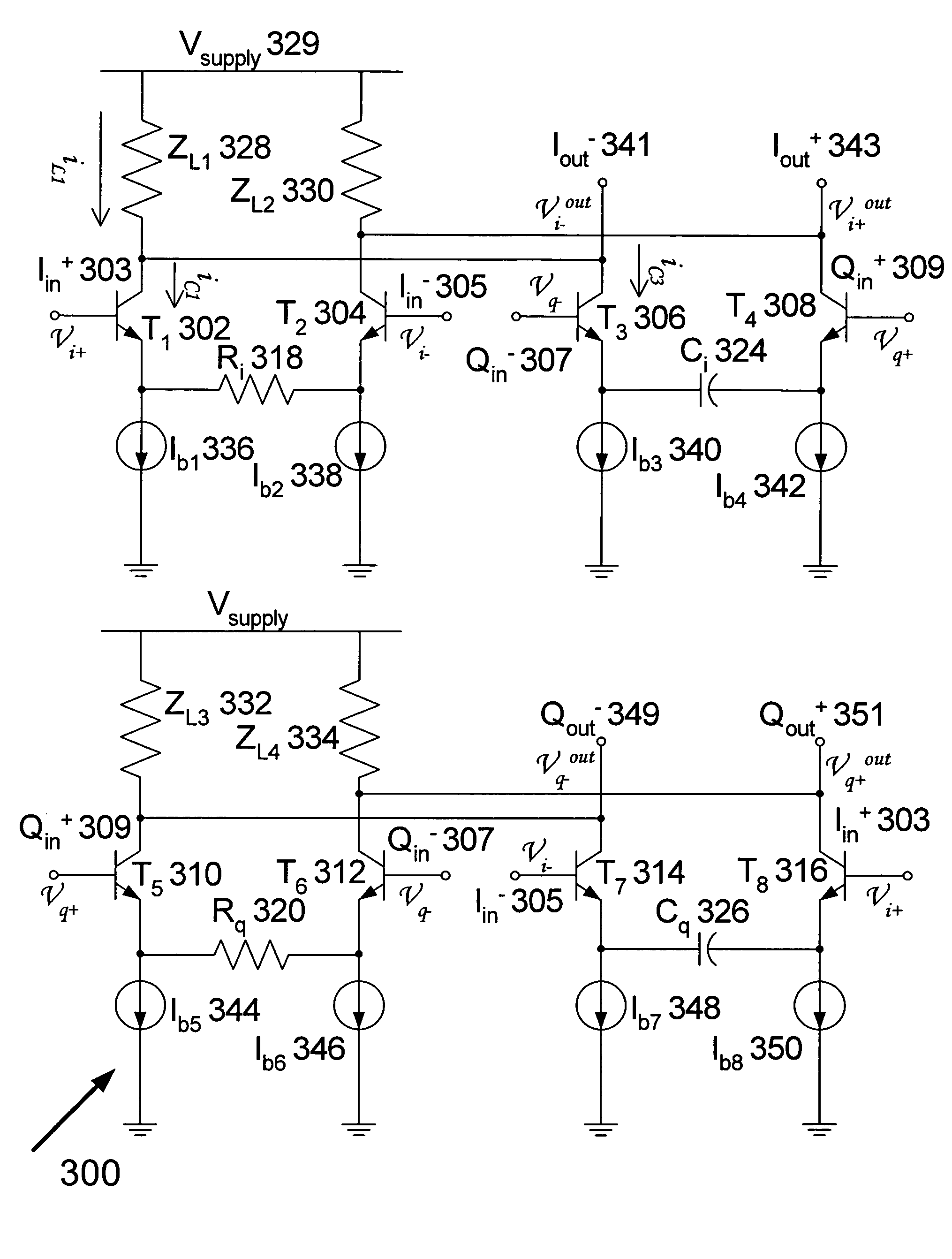
[0020]As disclosed below, the present invention provides methods and apparatuses for an active polyphase filter. In general, the active polyphase filter is composed of high-speed amplifiers with phase operations. The high-speed amplifiers include differential pairs with input signals being passed to the load with a phase shift of 90 degrees through a capacitor. Additionally, the output of the high-speed amplifiers provides buffering characteristics with large gain. Since the high-speed amplifiers use differential pairs, the amplifiers maintain functionality at high frequency.

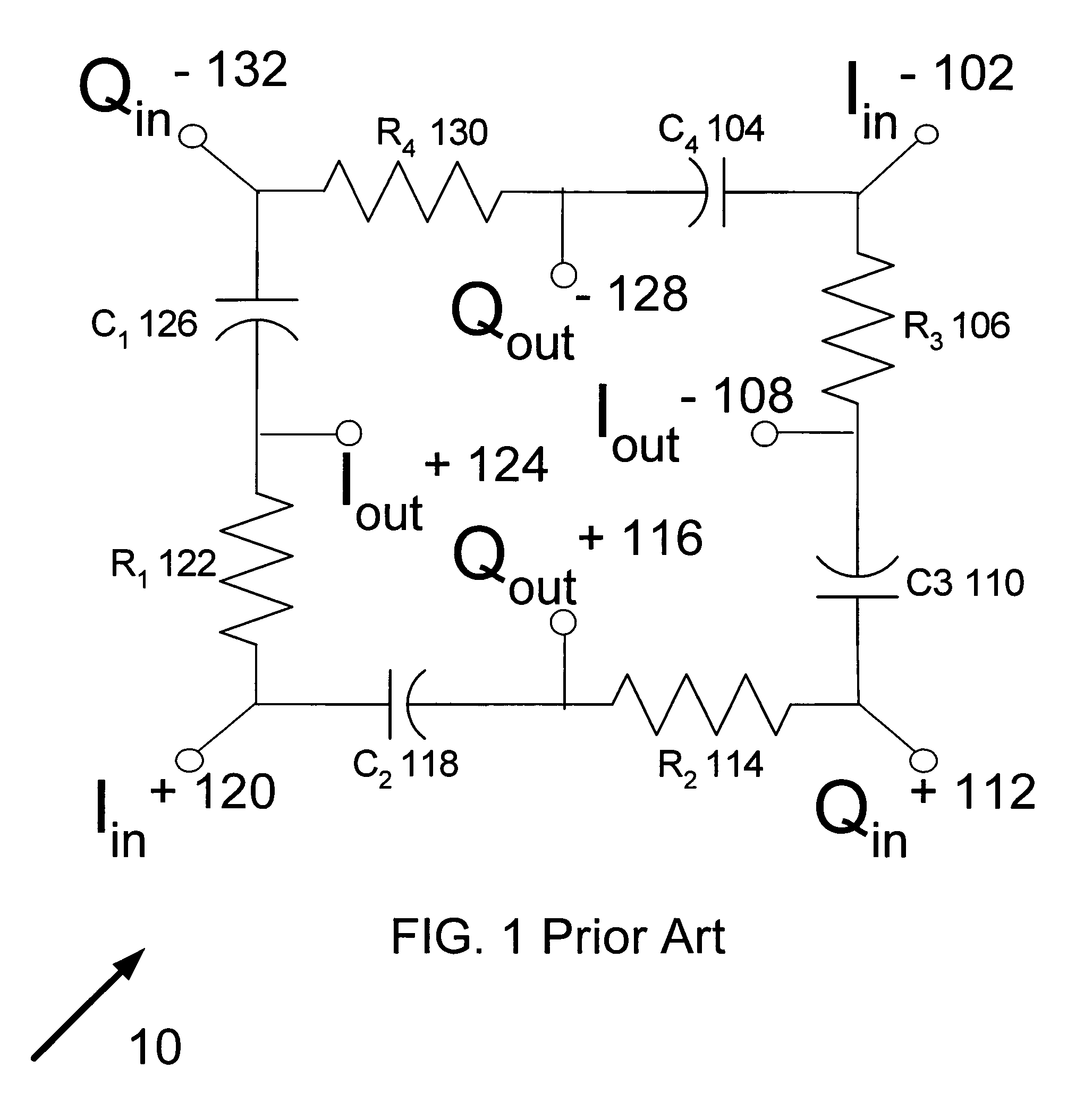
[0021]Throughout the description and the claims, the terms polyphase filter and quadrature filter may be used interchangeably. Quadrature filter is a special instance of a polyphase filter. Those skilled in the art will readily appreciate that the present implementation of a quadrature filter applies to polyphase filters. Accordingly, references to a quadrature filter are applicable to polyphase filter applicati...


PUM


Abstract

The present invention provides methods and apparatuses for a polyphase filter, comprising: a first and second cascoded differential amplifiers configured to receive a first and second differential signals, the first cascoded differential amplifier having a first resistor coupled between current legs of the first cascoded differential amplifier and the second cascoded differential amplifier having a first capacitor coupled between current legs of the second cascoded differential amplifier; and a third and fourth cascoded differential amplifiers configured to receive said first and said second differential signals, the third cascoded differential amplifier having a second resistor coupled between current legs of the third cascoded differential amplifier and the fourth cascoded differential amplifier having a second capacitor coupled between current legs of the fourth cascoded differential amplifier; wherein the first and second cascoded differential amplifiers are configured to provide a first differential output in response to the first and second differential signals and the third and fourth cascoded differential amplifiers are configured to provide a second differential output in response to the first and second differential signals.

Description

FIELD[0001]The present invention relates to polyphase filters and, more particularly, to methods and apparatuses for active polyphase filter buffer circuits.BACKGROUND[0002]Polyphase filters receive an N-phase or polyphase input signal and create an N-phase output signal. Quadrature filters, a particular type of polyphase filters, are well-known four-phase polyphase filters. Generally speaking, the inputs of a quadrature filter consist of four signal voltages of mutually equal value. The four signal voltages jointly constitutes a signal vector group with individual signal vectors succeeding one another in a given direction of rotation through phase angles of 90 degrees. The frequency of the polyphase signal may be positive or negative depending on a counter-clockwise or clockwise rotation. Typically, the 0 degree and 180 degree signal vectors are designated the +I and −I signals, and the 90 degree and 270 degree signal vectors are designated the +jQ and −jQ signals.[0003]Polyphase f...

Claims


Application Information

Patent Timeline
Patent Type & Authority Patents(United States)
IPC IPC(8): H03K5/00H04B1/10
CPCH03H11/22H03H2007/0192H03H2011/0494
Inventor CAO, KANYU MARKFAN, YIPINGLI, HONGYUCHAO, CHIEH-YUAN
Owner MEDIATEK INC
Why Eureka
Try Eureka