Method and apparatus for optical scanning capable of efficiently reducing an image surface distortion

Inactive Publication Date: 2007-09-18
RICOH KK
View PDF22 Cites 7 Cited by
  • Summary
  • Abstract
  • Description
  • Claims
  • Application Information

AI Technical Summary

Benefits of technology

[0013]In view of the foregoing, it is an object of the present invention to provide a novel optical sca

Problems solved by technology

This projecting apparatus has an optical arrangement of the post-objective type and has a drawback that the image surface distortion cannot be corrected, as in the case of the laser beam scanning.
The above-mentioned apparatuses described by Japanese Laid-Open Patent Application Publication, No. 2001-201710, have many constraints on the specifications required to the light imaging and scanning systems, and also have drawbac

Method used


Image

  • Method and apparatus for optical scanning capable of efficiently reducing an image surface distortion
  • Method and apparatus for optical scanning capable of efficiently reducing an image surface distortion
  • Method and apparatus for optical scanning capable of efficiently reducing an image surface distortion

Examples


Embodiment Construction

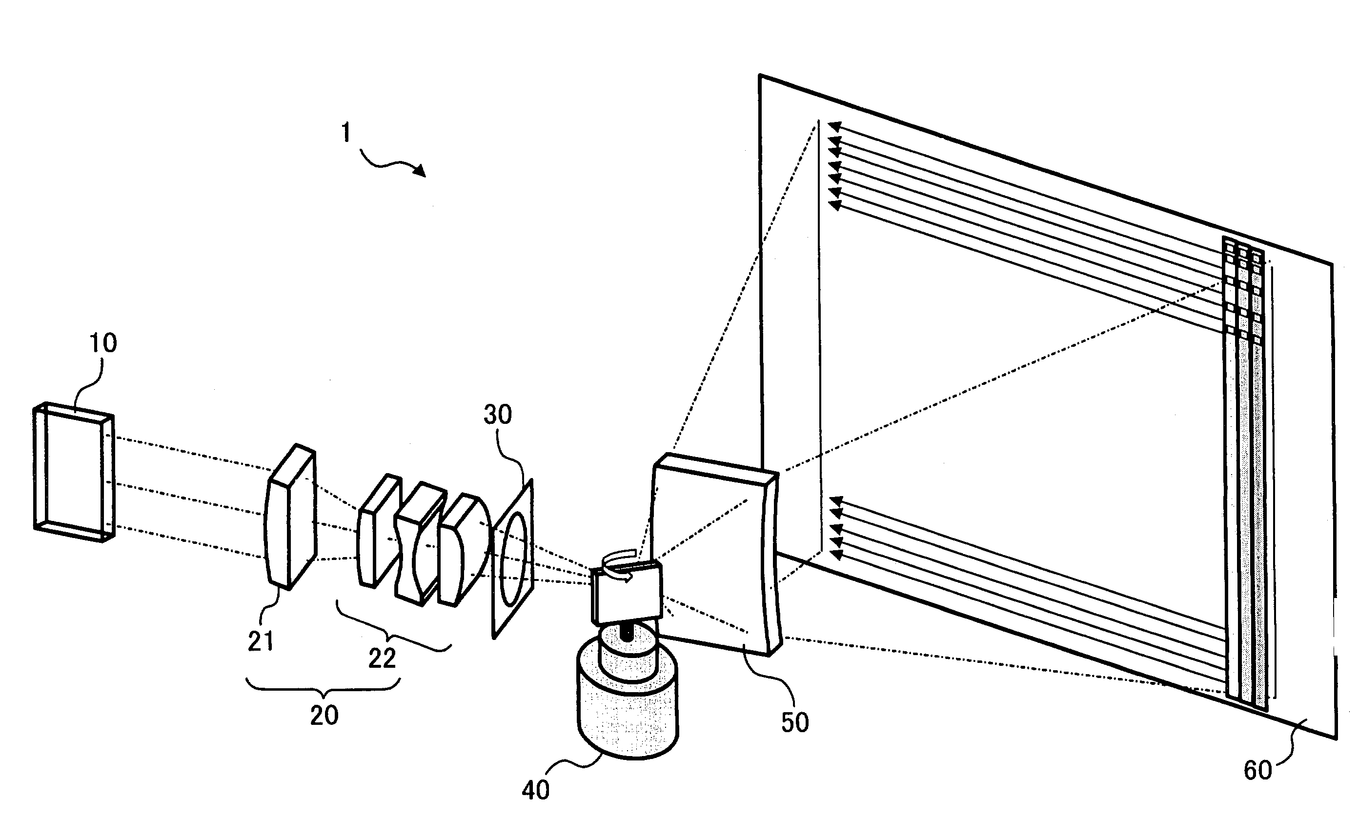
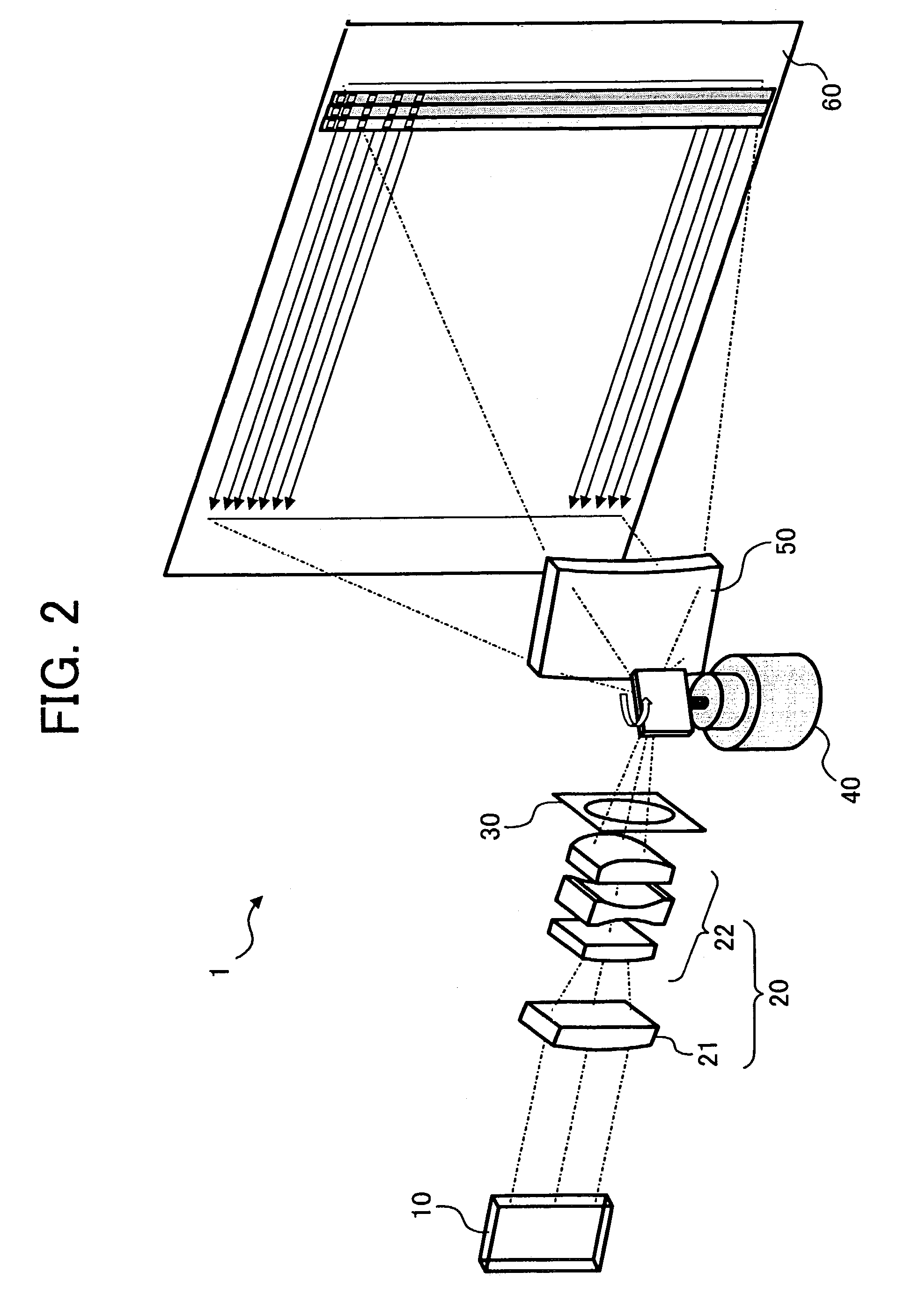
[0037]In describing preferred embodiments illustrated in the drawings, specific terminology is employed for the sake of clarity. However, the disclosure of this patent specification is not intended to be limited to the specific terminology so selected, and it is to be understood that each specific element includes all technical equivalents that operate in a similar manner. Referring now to the drawings, wherein like reference numerals designate identical or corresponding parts throughout the several views, and particularly to FIG. 2, an optical scanning apparatus 1 according to a preferred embodiment of the present invention is explained. The optical scanning apparatus 1 shown in FIG. 2 includes a light modulation device 10, a light imaging system 20, an aperture element 30, a light deflecting mechanism 40, a light scanning system 50, and an image screen 60. In this order, these components are disposed along a passage of light. The light modulation device 10 includes a self-light-em...


PUM


Abstract

An optical scanning apparatus includes mechanisms for light modulation, light imaging, light deflecting, and light scanning. The light modulation mechanism includes at least one light modulation device including light modulation elements, and is configured to emit modulated light. The light modulation elements are arranged in a single-dimension formation in a first direction orthogonal to a light axis of the modulated light. The light imaging mechanism transfers the modulated light as light of an object to form an image of the object on an image screen. The light deflecting mechanism deflects the light of the object in a direction orthogonal to the first direction and the axis of the light. The light scanning mechanism is disposed on a passage of the deflected light to scan that light.

Description

BACKGROUND OF THE INVENTION[0001]1. Field of the Invention[0002]The present invention relates to a method and apparatus for optical scanning, and more particularly to a method and apparatus for optical scanning capable of efficiently reducing an image surface distortion.[0003]2. Discussion of the Background[0004]A display apparatus for displaying an image by performing a line-by-line light scanning is well known, using a light deflecting mechanism such as a polygon mirror for deflecting light such as a laser beam generated by a point light source. For example, there are two types of known beam scanning optical systems; a post-objective type and a pre-objective type. FIG. 1A shows the post-objective type beam scanning optical system and FIG. 1B shows the pre-objective type beam scanning optical system. In the both systems, a deflective reflection surface of a light deflecting device 71 is arranged at a position orthogonal to the surface of the drawing and is rotatable or movable in a...

Claims


Application Information

Patent Timeline
IPC IPC(8): H04N1/46G02B26/08G02B13/22G02B26/10G02B26/12H04N9/31
CPCG02B26/123
Inventor KAWAMURA, ATSUSHIAOKI, MAGANE
Owner RICOH KK
Why Eureka
Try Eureka