Method for melting and forming micro lens array utilizing halftone mask photo etching

A technology of half-tone mask and microlens array, which is applied in the field of forming microlens arrays to achieve the effects of reducing surface distortion, simplifying the process, and eliminating burrs

Inactive Publication Date: 2008-02-27
INST OF OPTICS & ELECTRONICS - CHINESE ACAD OF SCI
View PDF3 Cites 0 Cited by
  • Summary
  • Abstract
  • Description
  • Claims
  • Application Information

AI Technical Summary

Problems solved by technology

[0006] The technical problem of the present invention is: to overcome the shortcomings of the existing microarray optical element forming methods, and to provide a halftone mask photolithography hot-melt microlens forming method that can quickly and effectively produce various microarray optical elements. Method In order to solve the problems encountered in the half-tone masking method, a method for forming micro-optical elements by combining the half-tone masking method with photolithographic hot-melt technology

Method used


Image

  • Method for melting and forming micro lens array utilizing halftone mask photo etching
  • Method for melting and forming micro lens array utilizing halftone mask photo etching

Examples


Embodiment 1

[0022] Example 1 is a continuous deep-relief microlens array with an aperture =1500 μm and an etching depth h=5 μm manufactured by the method of the present invention. Positive photoresist is used as the photolithography material. The production process is as follows:

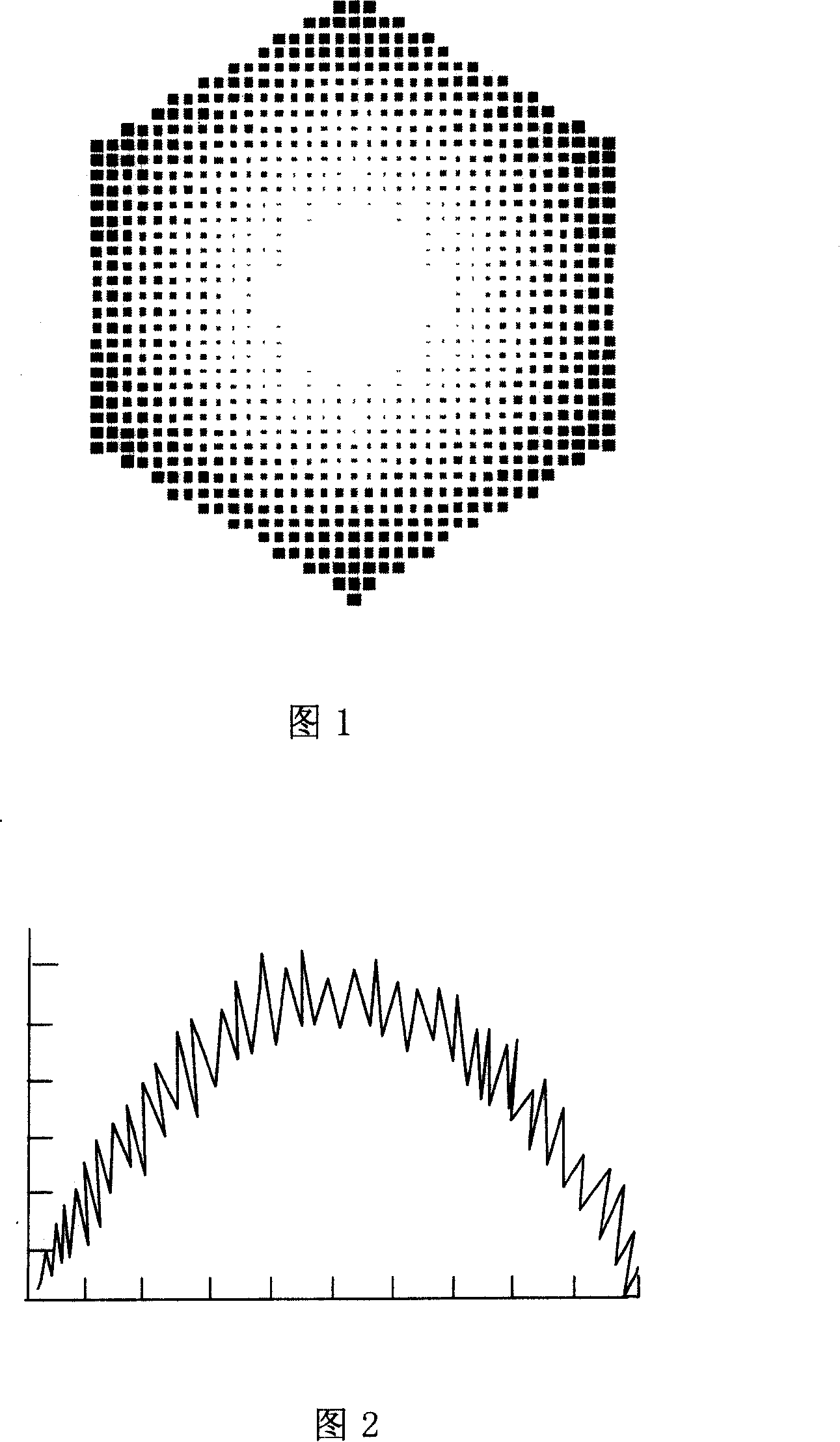
[0023] (1) First, design and fabricate a halftone photolithography mask according to the structural parameters and surface shape of the target microlens array, as shown in Figure 1. According to the relationship between the radius of curvature of the target microlens and the expected surface finish of the target microlens and the quantization accuracy of the halftone mask. It is calculated that to obtain a microstructure with a surface finish of less than 20 microns, the mask quantization accuracy needs to be 10.3 microns, and 10 microns is used in the experiment. Using this size as a quantization unit, the fluctuation of the target micro-relief is converted into a density function of the unit of the mask in diffe...


PUM


Abstract

This invention provides a new method for forming a micro-lens array by means of half tone mask and hot melt technique. Comparing with prior art, the method not only reduces greatly the demand of mask machine precision required by micro-structural formation, but also expand greatly processing scope of traditional half tone mask method, can prepare micro-structure with bilge of between several hundred nanometers and a hundred micrometers approximated, caliber of between 100 micrometers and several millimeters.

Description

Technical field [0001] The invention relates to a new method for forming a microlens array by using a halftone mask combined with a hot melt technology. Background technique [0002] Because of the advantages of light weight, small size, flexible design, and arrayability, microarray optical elements have been widely used in military, scientific research, and civilian fields. The manufacturing method of continuous relief microlens array has always been a research hotspot. Existing methods for forming microarray optical elements mainly include gray-scale masking method, electron beam, laser beam direct writing method, photolithography thermal melting method and so on. But these methods all have different degrees of defects. [0003] The working principle of electron beam and laser beam direct writing is similar. The two systems first focus an electron beam or a laser beam and expose the lithographic material point by point. The amount of energy obtained at a certain point on the re...

Claims


Application Information

Patent Timeline
Patent Type & Authority Patents(China)
IPC IPC(8): G02B3/00G03F7/20
Inventor 董小春杜春雷邱传凯李淑红赵泽宇
Owner INST OF OPTICS & ELECTRONICS - CHINESE ACAD OF SCI
Why Eureka
Try Eureka