Eureka AIR delivers breakthrough ideas for toughest innovation challenges, trusted by R&D personnel around the world.

Transmitter and receiver for spread-spectrum communication system, and modulation and demodulation methods thereof

a technology of spread-spectrum communication and transmitter, which is applied in the direction of multi-frequency code system, multiplex communication, orthogonal multiplex, etc., can solve the problems of low data transmission rate, unstable oscillating signal output of frequency synthesizer, and associated reduction of frequency switching wait time in frequency synthesizer, etc., to achieve the effect of improving communication quality through frequency hopping, reducing data transmission rate and poor communication quality

Inactive Publication Date: 2007-09-18
MITSUBISHI ELECTRIC CORP
View PDF17 Cites 75 Cited by
  • Summary
  • Abstract
  • Description
  • Claims
  • Application Information

AI Technical Summary

Benefits of technology

[0021]With this, it is possible to effect frequency-hopping spectrum spreading without controlling the switching between frequencies of a frequency synthesizer. A frequency switching wait time required in the related art for the frequency synthesizer to reach a stable operation is no longer required so that a data transmission rate is improved.
[0041]With this, the data transmission rate is reduced and the improvement in communication quality due to frequency hopping is enhanced when the effects from interference are serious and the communication quality is poor. Conversely, when the communication quality is favorable, the number of subcarriers used may be increased and the data transmission rate may be increased. Thus, the data transmission rate and the improvement in communication quality are suitably controlled depending on the conditions that occur in the transmission channel.

Problems solved by technology

Even when the frequency synthesizer capable of high-speed switching as disclosed in the above reference is used, however, the oscillated signal output from the frequency synthesizer is unstable immediately after the frequency switching.
When the hopping frequency RH is increased in the related-art spread-spectrum communication system as described above in accordance with an increase in required data transmission rate, associated reduction in the frequency switching wait time in the frequency synthesizer is limited due to hardware constraints.

Method used


Image

  • Transmitter and receiver for spread-spectrum communication system, and modulation and demodulation methods thereof
  • Transmitter and receiver for spread-spectrum communication system, and modulation and demodulation methods thereof
  • Transmitter and receiver for spread-spectrum communication system, and modulation and demodulation methods thereof

Examples


first embodiment

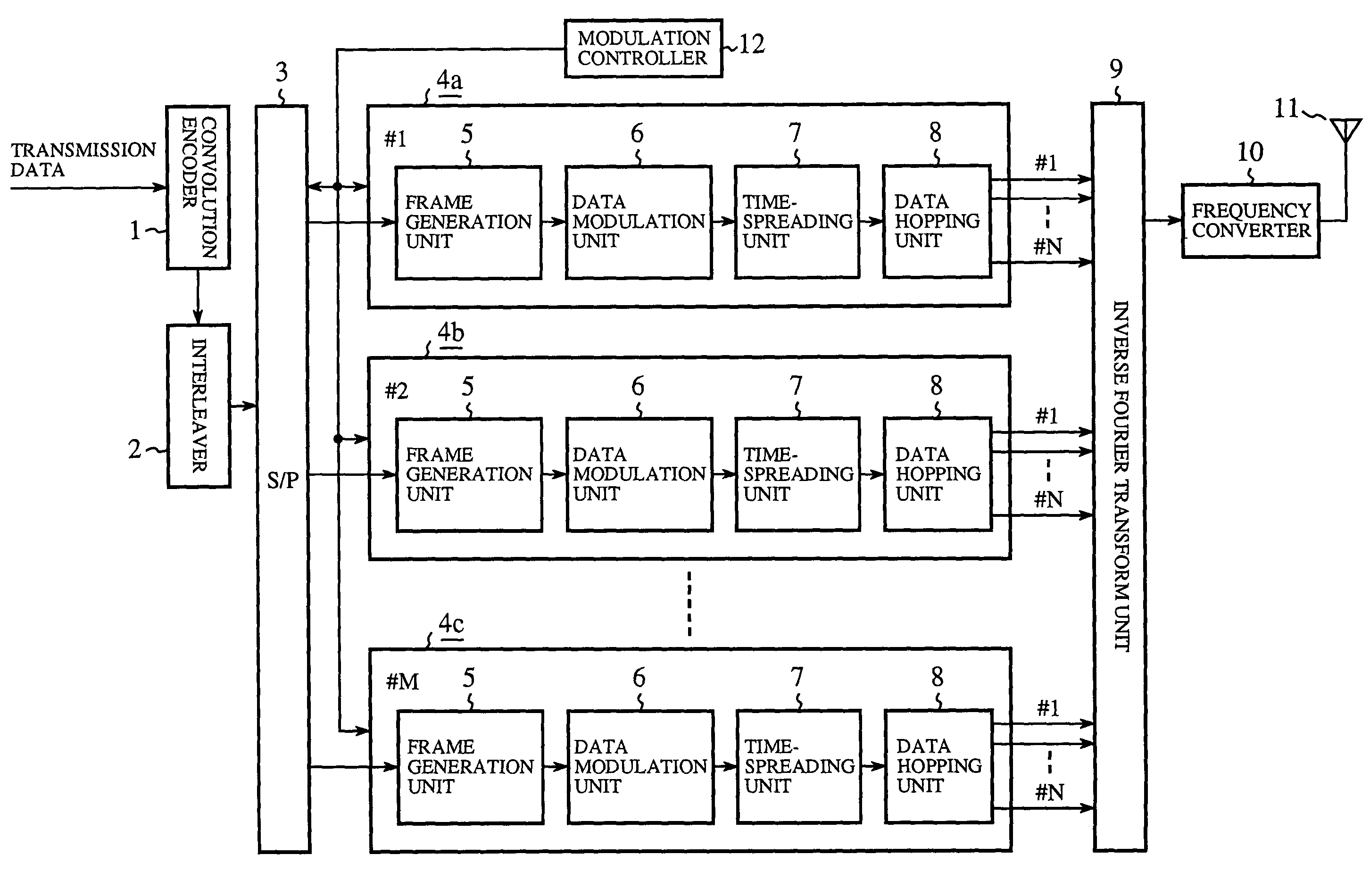
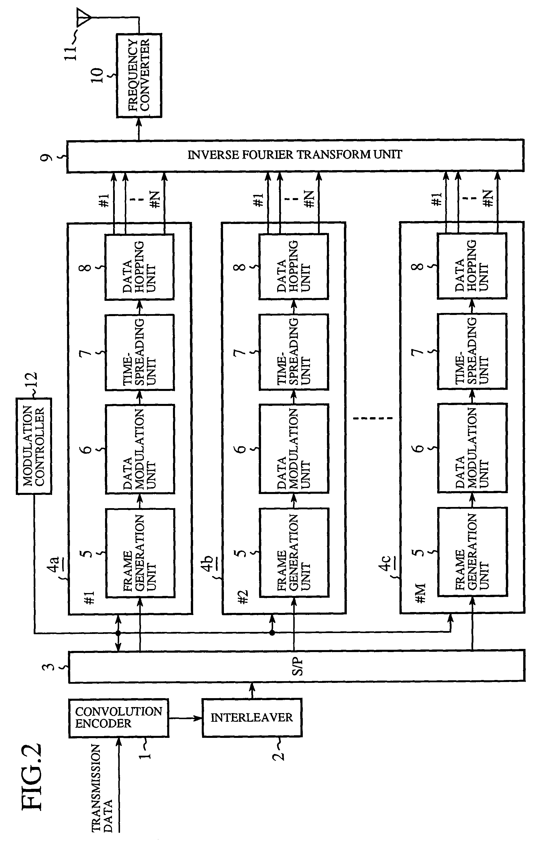
[0068]FIG. 2 is a block diagram showing a construction of a transmitter for a spread-spectrum communication system according to the first embodiment. Referring to FIG. 2, the system comprises a convolution encoder 1 for subjecting input transmission data to error-correction encoding, an interleaver 2 for interleaving the encoded transmission data and a serial-to-parallel conversion unit (hereinafter, referred to as S / P) splitting the interleaved transmission data and outputting the split data for transmission using a plurality of subchannels.

[0069]The system further comprises subchannel modulation processing units 4a, 4b and 4c for modulating the transmission data of the plurality of subchannels independently. Although the transmitter shown in FIG. 2 only shows the subchannel modulation processing units 4a, 4b and 4c, the system actually comprises a sufficient number of subchannel modulation processing units 4a, 4b, . . . 4c capable of parallel processing of the transmission data in...

second embodiment

[0121]In the receiver for a spread-spectrum communication system according to the second embodiment, each subchannel demodulation processing unit examines time-despread subchannel reception data to estimate a power of interference occurring in a transmission channel. By normalizing the subchannel reception data with the interference power before outputting the data for further processes, a favorable quality of communication is ensured even when the level of interference differs from subchannel to subchannel. The receiver according to the second embodiment only differs from the receiver according the first embodiment in that the interference power is estimated so that the subchannel reception data is normalized accordingly. The other aspects of the construction remains the same so that the description thereof is omitted by denoting the corresponding elements by the same reference numerals.

[0122]The transmitter used in the spread-spectrum communication system according to the second e...

third embodiment

[0133]In the first embodiment, the bit error performance is improved by processing the data for transmission using both frequency-hopping and time-spreading spectrum spreading using inverse Fourier transform. In the spread-spectrum communication system according to the third embodiment, the data is first subjected to frequency-hopping spectrum spreading using inverse Fourier transform in each subchannel. Subsequently, a guard interval is inserted to eliminate adverse effects from delay wave occurring in the transmission channel so that the bit error performance is improved.

[0134]The description that follows highlights the transmitter and the receiver of the spread-spectrum communication system according to the third embodiment. The transmitter and the receiver according to the third embodiment only differ from the transmitter and the receiver according to the first embodiment in the construction of the subchannel modulation processing units and the subchannel demodulation processing...


PUM


Abstract

A data hopping device is provided with a hopping generation unit and a data selection unit, the hopping pattern generation unit generating a predetermined hopping pattern, and the data selection unit outputs a plurality of subcarrier transmission signals corresponding to respective subcarriers, by receiving transmission data and outputting only the data carried in the subcarrier designated by the hopping pattern as the subcarrier transmission signal, while maintaining the other subcarrier transmission signals at a zero output level. An inverse Fourier transform device subjects the entirety of subcarrier reception signals output from the data selection unit to inverse Fourier transform and outputs frequency-hopped spread-spectrum transmission signals.

Description

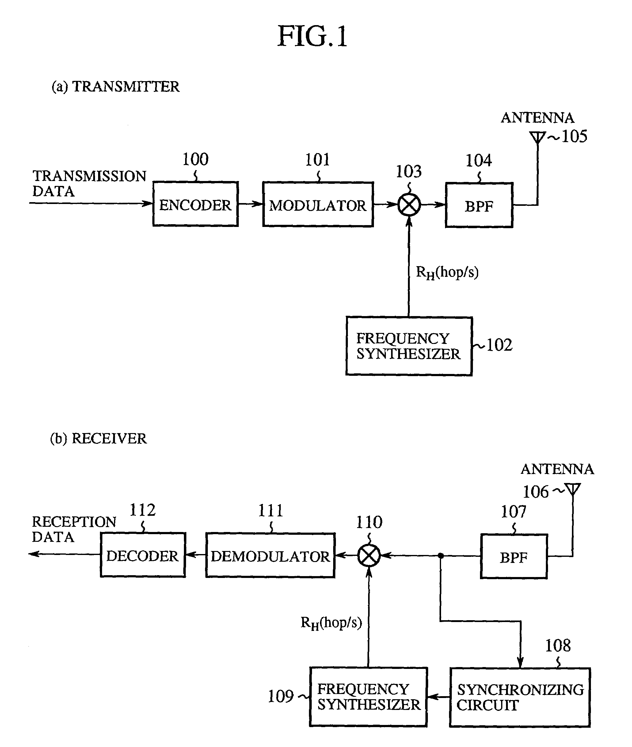
TECHNICAL FIELD[0001]The present invention generally relates to transmitters, receivers and modulation and demodulation methods for a mobile spread-spectrum communication system.BACKGROUND ART[0002]A form of spectrum spreading wireless communication known as frequency hopping is widely used. In frequency-hopping systems for spreading spectrums, when modulated data are up-converted to a radio frequency band (RF band) using an intermediate frequency band (IF band), the frequency of a locally oscillated signal is made to hop continually over a wide frequency range.[0003]FIG. 1 is a block diagram showing a construction of a spread-spectrum communication system of a related-art frequency-hopping scheme shown in Yokoyama “Spread-spectrum communication system” Kagaku Gjutsu Shuppan, May, 1988:564-566. In the following paragraphs, a description will be given of the related-art spread-spectrum communication system with reference to FIG. 1.[0004]A transmitter shown in FIG. 1(a) comprises an e...

Claims


Application Information

Patent Timeline
IPC IPC(8): H04B1/69H04B1/707H04B1/713H04L1/00H04B1/692H04B1/7115H04B1/7143H04J11/00H04L5/02H04L7/00H04L27/26
CPCH04B1/7136H04B1/7143H04B1/7156H04L5/026H04L27/2602H04B2001/71367H04B2001/71563H04L27/2634
Inventor SANO, HIROYASUKUBO, HIROSHI
Owner MITSUBISHI ELECTRIC CORP
Why Eureka
Eureka Blog
Learn More