Method to transmit bits of data over a bus

a bus and data technology, applied in the field of computing technology, can solve the problems of limited data transmission through the bus, severe limits on the amount of data throughput that can be transmitted through the bus, and inability to send more than 2 bits per clock cycle in the general direction of synchronous/start-stop systems,

Inactive Publication Date: 2007-09-18
RPX CORP
View PDF1 Cites 15 Cited by
  • Summary
  • Abstract
  • Description
  • Claims
  • Application Information

AI Technical Summary

Benefits of technology

[0015]Broadly speaking, the present invention fills these needs by providing computer implemented methods for optimizing data transfer, speeds through the intelligent use of multilevel coding to transfer multiple bits per signal level thereby enabling the transmission of at least 4 bits every clock cycle.
[0021]The advantages of the present invention are numerous. Specifically, by having multilevel coding of data where a voltage amplitude of a signal level can signify a particular bit combination, multiple bits of data may be sent during each of the clock edges (e.g., a combination of bits may be sent for every half cycle during a double clock data transmission). Therefore, more data may be transmitted than previously possible thereby optimizing data management in a computer system. As a result, data transmission speeds may no longer be a bottleneck of computing systems.

Problems solved by technology

Therefore, at maximum, prior art systems are not generally capable of sending more than 2 bits per full clock cycle.
This severely limits the amount of data throughput that may be transmitted through a bus such as, for example, the SCSI bus 20.
Unfortunately, after a certain frequency is reached, data transmission through a bus is limited due to numerous constraints.
Typically, the cutoff frequency is 320 MHz, and any frequency beyond 320 MHz is very difficult to utilize.
Therefore, even with double clocking, it is very difficult to achieve greater than a data transfer rate of 640 Mbytes per second in SCSI systems.
Unfortunately, when the cutoff frequency is reached, the signal becomes so degraded due to increased noise levels that it is extremely difficult if not impossible to tell if the digital signal is transmitting a “0” or a “1”.
Consequently, after a certain frequency is reached, data throughput speed is limited and data transmission speeds can be a bottleneck in data processing operations.

Method used


Image

  • Method to transmit bits of data over a bus
  • Method to transmit bits of data over a bus
  • Method to transmit bits of data over a bus

Examples


Embodiment Construction

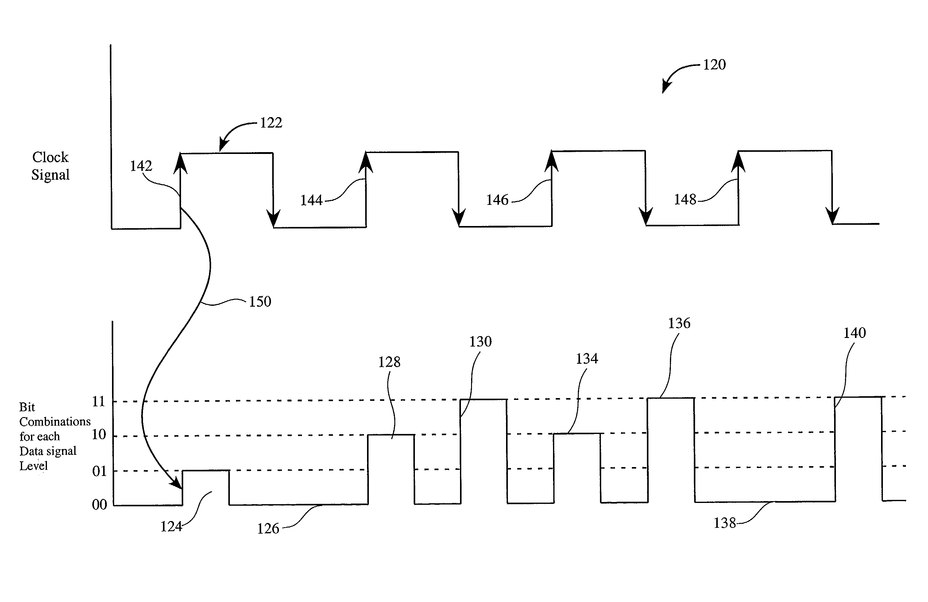
[0031]An invention is described for a method of expanding a bus so an optimized amount of data may be transmitted in a computer system. In this methodology, multilevel coding is utilized to transmit multiple bits of data per signal level in a digital data transmission system. It will be obvious, however, to one skilled in the art, that the present invention may be practiced without some or all of these specific details. In other instances, well known process operations have not been described in detail in order not to unnecessarily obscure the present invention.

[0032]The data transmission methodology described herein enables many times more data to be sent in a same data transmission media than prior art systems. The multilevel coding described herein enables multiple data voltage levels to be utilized to transport a larger amount of data than previously possible. In one embodiment, the multilevel coding has four levels of voltage each signifying a different data content. Therefore ...


PUM


Abstract

A method to increase data transmission over a SCSI bus is provided including assigning a voltage level to each one of a plurality of bit combinations, and generating a signal level having the voltage level corresponding to one of the plurality of bit combinations sought to be transmitted. The method also includes transmitting the signal level to a receiver to send one of the plurality of bit combinations during a data transmission interval.

Description

BACKGROUND OF THE INVENTION[0001]1. Field of the Invention[0002]This invention relates generally to the field of computing technology and more particularly concerns the optimization of data transfer rates by sending more data during a clock period by using multilevel coding of data signals.[0003]2. Description of the Related Art[0004]The art of networking computers has evolved over the years to bring computer users a rich communication and data sharing experience. Typically, in a network, numerous devices may be connected to a computer to maximize computing power and efficiency. As is well known, new levels of sophisticated communication technologies enable users to share information across both large and small networks.[0005]In computer technology, computers may intercommunicate through data transmission through a network connecting numerous computers. For example, in a typical computer system, a computer system may include a computer and peripheral devices such as, for example, st...

Claims


Application Information

Patent Timeline
Patent Type & Authority Patents(United States)
IPC IPC(8): H04L25/34
CPCH04L25/4917
Inventor MAHMOUD, FADI A.
Owner RPX CORP
Why Eureka
Try Eureka