Hardware looping mechanism and method for efficient execution of discontinuity instructions
- Summary
- Abstract
- Description
- Claims
- Application Information
AI Technical Summary
Benefits of technology
Problems solved by technology
Method used
Image
Examples
example # 1
EXAMPLE #1
A “Tight” Loop
[0079]In general, a “tight” loop may be described as a set of program instructions containing a relatively small number of loop instructions. Due to the relatively small number of instructions included, all “tight” loop instructions may be grouped and executed in the same processor cycle. As shown in FIGS. 7 and 8, for example, a “tight” loop may include two loop instructions (i0, i1) followed by the Again instruction (agn0). A lesser or greater number of tight loop instructions may be included in alternative embodiments.
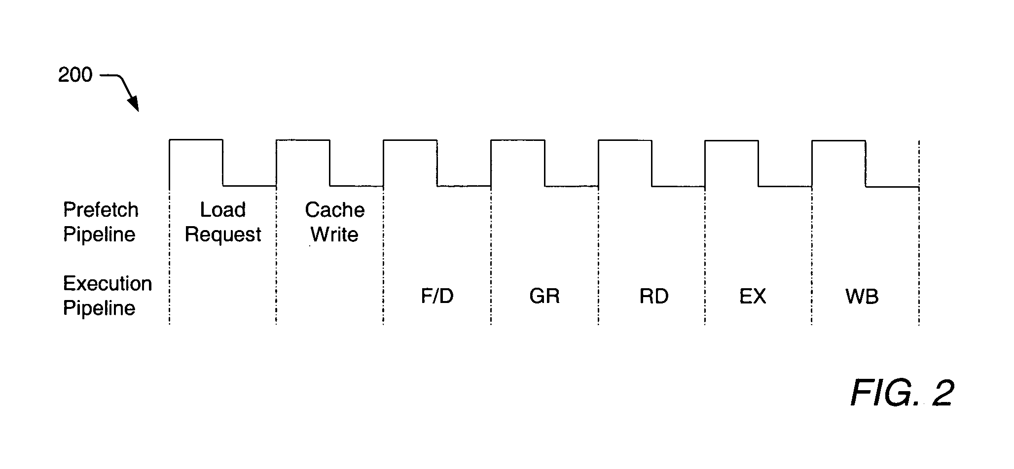
[0080]FIG. 8 illustrates how the tight loop may be executed in accordance with a conventional method. As shown in FIG. 8, the first two loop instructions may begin a first iteration of the loop upon entering the F / D stage during a first cycle of the pipeline (i.e., cycle ‘n’). Since only two instructions reside within the loop, the first iteration ends when the agn0 instruction is detected in the F / D stage during the second cycle of the pipel...
example # 2
EXAMPLE #2
A Nested Loop
[0083]As noted above, the hardware looping mechanism and method described herein may be applied to any number and / or type of discontinuity instructions. FIGS. 9A and 9B illustrate one manner in which a nested loop may be handled by the hardware looping mechanism. In other words, FIGS. 9A and 9B illustrate how a “branch-within-the-loop” instruction may be handled. As shown in FIG. 9A, inner and outer loops may each be provided with two instructions. In the embodiment of FIG. 9B, the inner loop (containing loop instructions i2, i3 and the agn0 instruction) may be implicitly executed without re-issuing the agn0 instruction into the pipeline for each new iteration of the inner loop. The implicit execution of the inner loop is illustrated in FIG. 9B during pipeline cycles n+2, n+3, n+4, and again during pipeline cycles n+8, n+9, n+10. During these cycles, the end-of-branch flag is used, in place of the agn0 instruction, to signify the completion of an iteration. Ho...
example # 3
EXAMPLE #3
A Branch-Out-of-Loop Instruction Near the End of a Loop Construct
[0085]The following program code illustrates some of the limitations placed on the DO looping mechanism:
[0086]
DO #3, OuterLoop; beginning of outer loopPUSH LC; save the loop count (LC)PUSH LA; save the loop address (LA)DO X0, InnerLoop; beginning of inner loop(instructions)ASL A; arithmetic shift left(instructions)InnerLoop:; end of inner loop ADD A, B; add two accumulators POP LA; retrieve the last address of the outer loop POP LC; retrieve the loop count of the outer loop NOP; three NOP instructions are required so that LC NOP; can be properly updated before it is decremented NOP; by the last instruction.OuterLoop:; end of outer loop
First of all, the DO looping mechanism requires at least three NOP (no operation instructions) to be included after the POP LC instruction. This requirement is enforced to ensure that there is ample time to update the loop count before it is decremented by the last instruction i...
PUM
 Abstract
Description
Claims
Application Information
 - R&D
- Intellectual Property
- Life Sciences
- Materials
- Tech Scout
- Unparalleled Data Quality
- Higher Quality Content
- 60% Fewer Hallucinations
Browse by: Latest US Patents, China's latest patents, Technical Efficacy Thesaurus, Application Domain, Technology Topic, Popular Technical Reports.
© 2025 PatSnap. All rights reserved.Legal|Privacy policy|Modern Slavery Act Transparency Statement|Sitemap|About US| Contact US: help@patsnap.com


