
Method for manufacturing a multimode fiber pump power combiner

a technology of optical fiber and combiner, which is applied in the field of pumping optical fiber amplifiers, can solve the problems of optical loss, inefficiency of transfer, and inability to achieve the effect of eliminating losses due to stress-induced polarization changes

Inactive Publication Date: 2007-09-25
COHERENT INC
View PDF1 Cites 69 Cited by
  • Summary
  • Abstract
  • Description
  • Claims
  • Application Information

AI Technical Summary

Benefits of technology

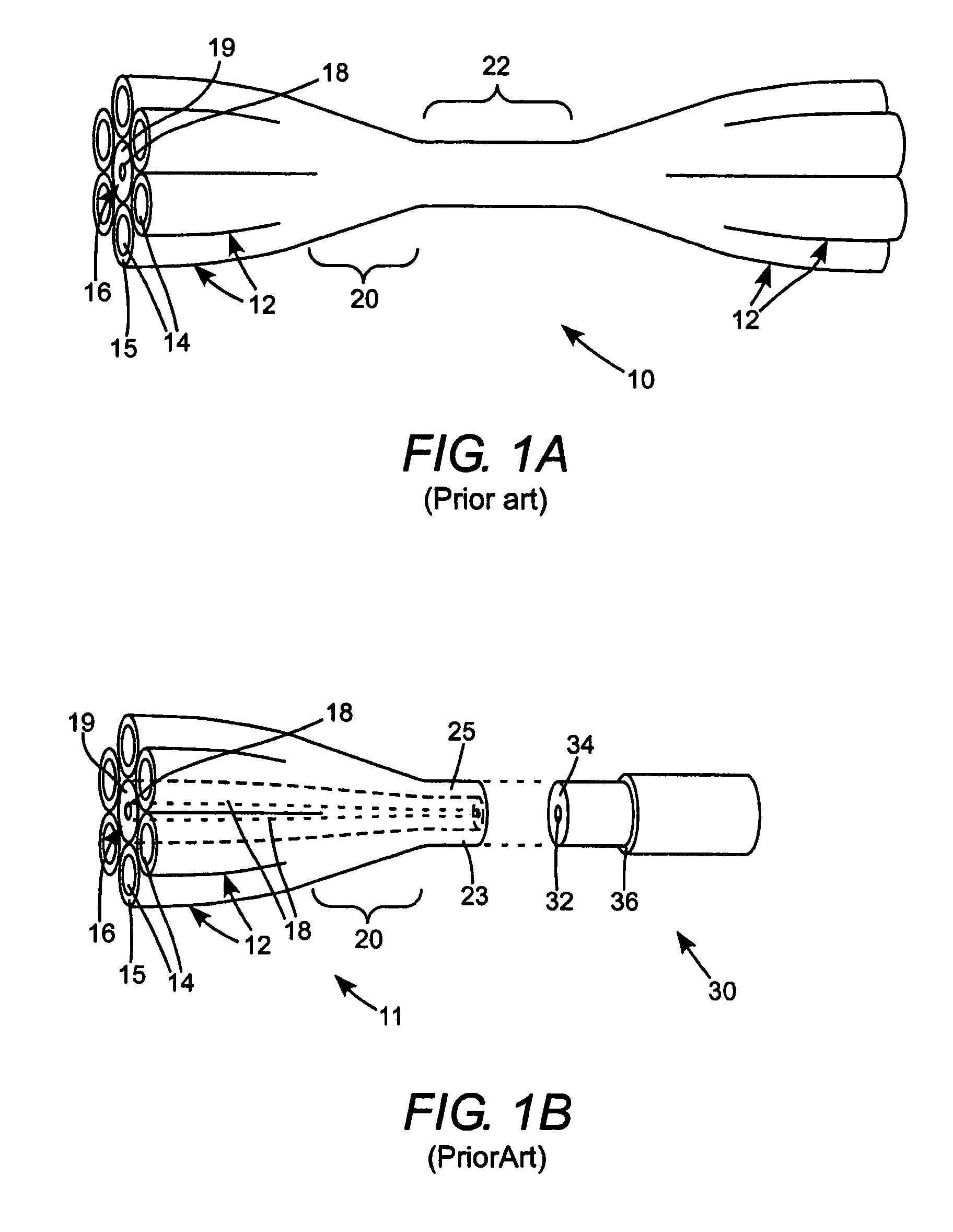
[0014]Deficiencies of the prior-art are overcome by adding a low mode core to a multimode fiber combiner after the multimode fibers are tapered and fused together. By this approach, the low-mode core is not tapered and can be matched in diameter to an amplifier core. Further, as no twisting force is applied to the core, above described losses due to stress induced polarization changes can be essentially eliminated.

Problems solved by technology

A problem with the signal and pump light coupling of DiGiovanni et al. is that transfer of signal light energy from the low-mode core of the combiner to the low-mode core of the amplifier fiber is often inefficient.
This transfer inefficiency results from two effects.
A first of these effects is optical loss due to a mismatch between the mode-field diameter (core diameter) of the combiner and the mode-field diameter (core diameter) of the amplifier.
Such a twist, however, induces stresses in the central fiber and may cause loss of signal power.
When the central fiber is a single-mode, polarization-maintaining, or large-mode area fiber with low numerical aperture, the stress induced by the twisting adversely affects both the 140 degree of polarization and loss.

Method used


Image

  • Method for manufacturing a multimode fiber pump power combiner
  • Method for manufacturing a multimode fiber pump power combiner
  • Method for manufacturing a multimode fiber pump power combiner

Examples


Embodiment Construction

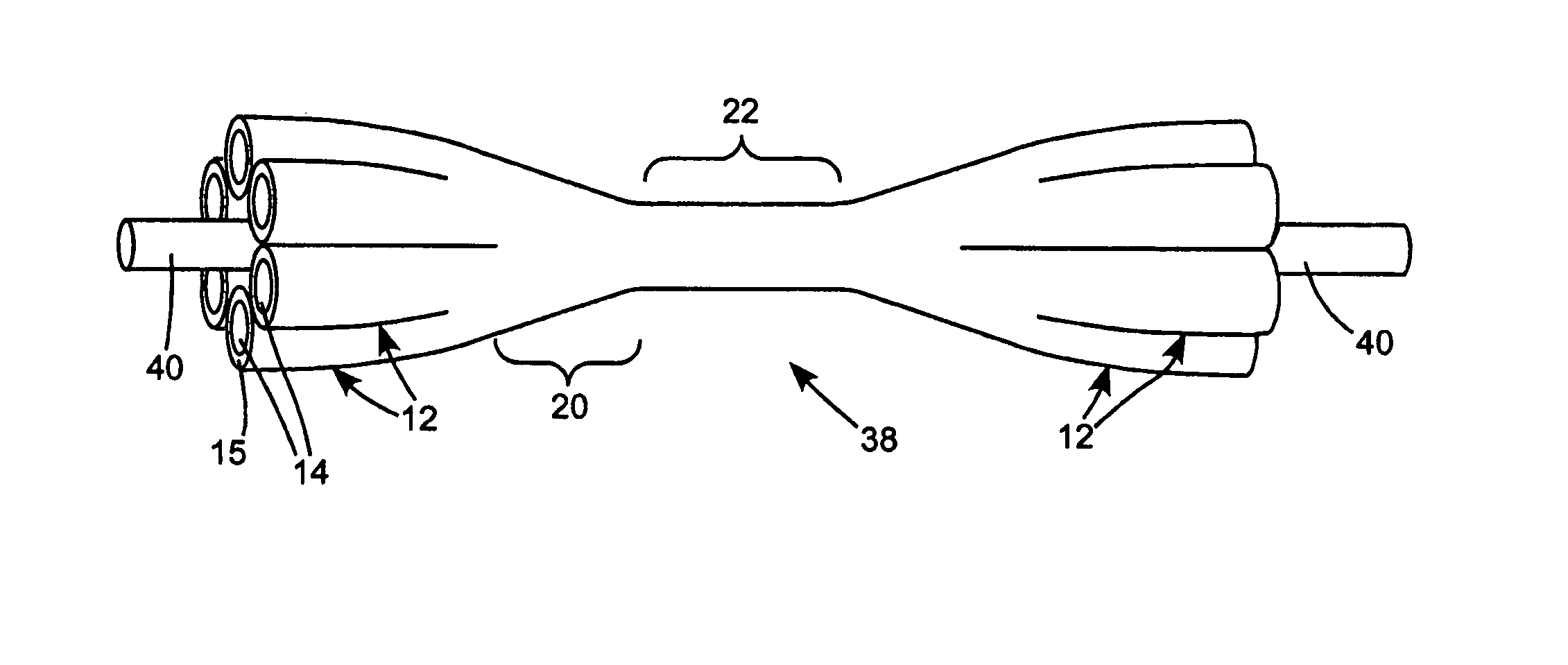
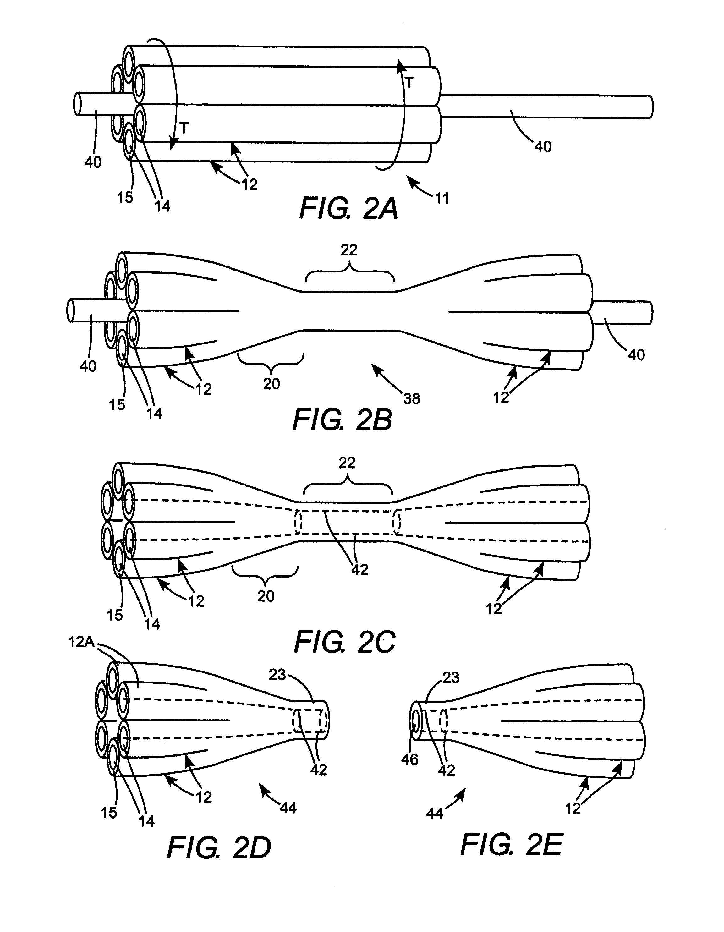
[0024]Returning now to the drawings, in which like features are designated by like reference numerals, a description of one preferred embodiment of a method in accordance with the present invention for assembling a multimode pump light fiber combiner including a signal light carrying, low-mode core having the same diameter at input and output ends thereof is set forth below with reference to FIGS. 2A through 2H.

[0025]In one step of the inventive method (see FIG. 2A) a plurality of multimode fibers 12 (here, six fibers) is grouped into a straight bundle 11, around a metal wire 40 having a higher melting point than the material of the optical fibers and preferably having a coefficient of expansion greater than that of the material of the fibers. Suitable metals for wire 40 include platinum (Pt) and tungsten (W), with tungsten being particularly preferred.

[0026]Bundled fibers 12 are selectively heated between opposite ends of the bundle to a temperature at which the multimode fibers wi...


PUM

PropertyMeasurementUnit
Diameteraaaaaaaaaa
Temperatureaaaaaaaaaa
Lengthaaaaaaaaaa

Abstract

A multimode to low-mode optical fiber is constructed by forming a plurality of multimode optical fibers into a fiber bundle. The bundle is then selectively heated and drawn to form a bi-tapered fiber bundle having a central straight portion in which the multimode fibers are fused into a single length of fiber. During the drawing step, measures are taken to provide an aperture extending through the bi-tapered bundle, including the single straight portion of the bundle. An optical fiber having a low-mode or single-mode core is inserted through the aperture into the straight section of the bi-tapered bundle. The bi-tapered bundle and the low-mode core fiber are heated to a temperature at which cladding of the low-mode core fiber fuses to the straight portion of the bi-tapered bundle. The bi-tapered bundle is then cleaved in the straight portion to provide the multimode to low-mode optical fiber combiner. In one example, the multimode fiber bundle is formed around a metal wire before the drawing operation. After the drawing operation the wire is extracted from the bi-tapered bundle leaving the aperture in the bi-tapered bundle.

Description

TECHNICAL FIELD OF THE INVENTION[0001]The present invention relates generally to methods of pumping optical fiber amplifiers. The invention relates in particular to pumping optical fiber amplifiers with light delivered via a plurality of multimode optical fibers.DISCUSSION OF BACKGROUND ART[0002]A common form of optical fiber amplifier includes a doped low-mode core surrounded by an inner cladding layer and an outer cladding layer. Optical pump light, is directed into the inner cladding layer, propagates along the fiber and is progressively absorbed in the doped core. The absorbed pump light energizes the core to provide optical gain. Light to be amplified, either from a fiber laser or from another fiber amplifier is coupled into the low-mode core of the amplifier fiber and is amplified as it propagates along the core.[0003]The terminology “low-mode” as applied to optical fibers described herein refers to a fiber having a core diameter sufficiently small compared with the wavelength...

Claims


Application Information

Patent Timeline
IPC IPC(8): C03B37/028
CPCG02B6/2835G02B6/02023H01S3/094019H01S3/094007
Inventor ANIKITCHEV, SERGUEI G.LINDSAY, KEVIN ELTONSTARODOUMOV, ANDREI
Owner COHERENT INC
Learn More