Steam enhanced double piston cycle engine

a double-piston cycle engine and steam technology, applied in the direction of machines/engines, mechanical equipment, transportation and packaging, etc., can solve the problems of inability to increase efficiencies, more than one-half of the potential fuel thermal energy created by conventional engines disperse through the engine structure without adding any useful mechanical work, and achieve the effect of increasing engine efficiency, facilitating efficient transfer of compressed gas, and increasing power

Active Publication Date: 2007-09-25
TOUR ENGINE INC
View PDF34 Cites 17 Cited by
  • Summary
  • Abstract
  • Description
  • Claims
  • Application Information

AI Technical Summary

Benefits of technology

[0023]In another embodiment, a method of improving combustion engine efficiency includes separating the intake and compression chamber (cool strokes) from the combustion and exhaust chamber (hot strokes), and thus enabling reduced temperature during intake and compression strokes and increased temperature during the combustion stroke, thereby increasing engine efficiency.
[0024]In a further embodiment, a method of improving engine efficiency includes minimizing or reducing the temperature during intake and compression strokes. The lower the incoming and compressed air / charge temperature is, the higher the engine efficiency will be.
[0026]In a further embodiment, a dual piston combustion engine is provided that greatly reduces external cooling requirements which in turn increases the potential heat available for heat output work conversion during the power stroke, which also burns fuel more efficiently and thereby decreases harmful emissions.
[0028]In another embodiment, a steam enhanced dual piston combustion engine additionally comprises a ring-shaped chamber in the combustion cylinder to receive compressed gases and / or liquids utilizing excess engine heat to produce additional power and increase engine efficiency. In a further embodiment a steam enhanced dual piston combustion engine additionally comprises a ring-shaped chamber in the compression cylinder to facilitate efficient transfer of compressed gases and / or liquids to the steam chamber. In an additional embodiment, a steam enhanced dual piston combustion engine contains two separate power producing systems, with a primary system utilizing fuel-air combustion and secondary system utilizing excess engine heat for steam power generation.

Problems solved by technology

The main problem with a conventional internal combustion engine is low fuel efficiency.
It is estimated that more than one half of the potential fuel thermal energy created by conventional engines dissipates through the engine structure without adding any useful mechanical work.
Another problem with conventional internal combustion engines is their inability to increase efficiencies while using heat regeneration or recycling methods to provide higher combustion temperatures.
Another reason why conventional engines suffer from efficiency problems is that the high-temperature in the cylinder during the intake and compression strokes makes the piston work harder and, hence, less efficient during these strokes.
Another disadvantage associated with existing internal combustion engines is their inability to further increase combustion temperatures and compression ratios; although raising chamber temperatures during the power stroke and increasing compression ratios would improve efficiencies.
Another problem with conventional engines is their incomplete chemical combustion process causing harmful exhaust emissions.
While these devices may be suitable for the particular purpose to which they address, they are not as efficient as the proposed SE-DPCE that utilizes temperature differentiated dual cylinders that divide the conventional four strokes of a piston into two low temperature strokes (intake and compression) and two high temperature strokes (power and exhaust), performed by each of the respective dual pistons, while further utilizing the heat generated by the high temperature strokes to generate steam, which is used to convert additional thermal energy to mechanical energy.
However, these references fail to disclose how to differentiate cylinder temperatures to effectively isolate the firing (power) cylinders from the compression cylinders and from the surrounding environment.
The references further fail to disclose how to minimize mutual temperature influence between the cylinders and the surrounding environment.
In addition, the references fail to disclose engine improvements that further raise the temperature of the firing cylinder and lower the temperature of the compression cylinder beyond that of conventional combustion engine cylinders to enhance engine efficiency and performance.
Additionally, none of these prior art references discussed above teach an opposed or “V” cylinder and crankshaft configuration that minimizes dead space between cylinders while isolating the cylinders to maintain an improved temperature differential between the cylinders.
Finally, none of these prior art references disclose splitting the combustion / power chamber into two separate chambers and utilizing steam energy in an outer chamber for additional engine efficiency and work.
Additionally, none of the prior art references disclose or suggest a secondary system, enveloping the primary combustion chamber, that converts the excessive thermal energy produced by the hot chamber into additional kinetic energy.
Clarke also fails to disclose forming a separate chamber for utilizing additional energy (e.g., heated air or steam) generated by excess engine heat.
However, elevated temperatures in the entire Thomas engine reside not only throughout the combustion and exhaust strokes, but also during part of the compression stroke.
Further, Thomas fails to disclose a method of isolating the engine cylinders in an opposed or “V” configuration to permit improved temperature differentiation and discloses an engine containing substantial dead space in the air intake port connecting the cylinders.
Finally, Thomas fails to disclose forming a separate chamber for utilizing additional energy (e.g., heated air or steam) generated by excess engine heat.

Method used


Image

  • Steam enhanced double piston cycle engine
  • Steam enhanced double piston cycle engine
  • Steam enhanced double piston cycle engine

Examples


Embodiment Construction

[0063]The invention is described in detail below with reference to the figures, wherein similar elements are referenced with similar numerals throughout. It is understood that the figures are not necessarily drawn to scale. Nor do they necessarily show all the details of the various exemplary embodiments illustrated. Rather, they merely show certain features and elements to provide an enabling description of the exemplary embodiments of the invention.

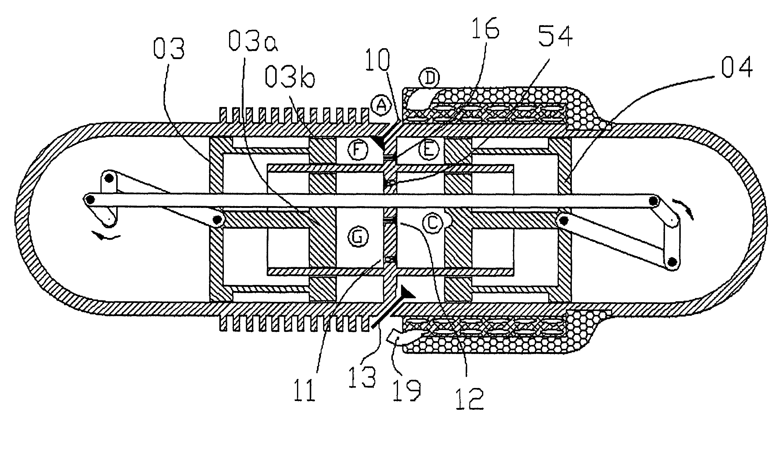
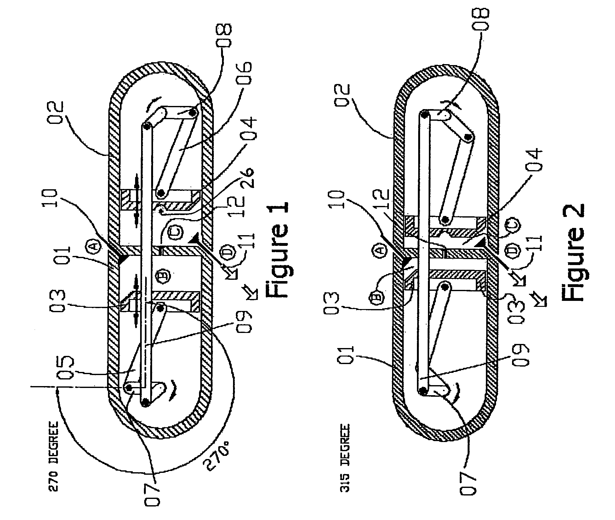
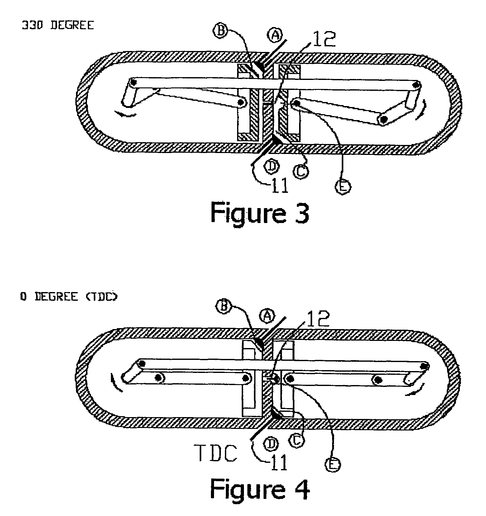
[0064]Referring to FIG. 1, in accordance with one embodiment of the invention, a DPCE cylinder includes: a compression cylinder 01, a power cylinder 02, a compression piston 03, a power piston 04, two respective piston connecting rods 05 and 06, a compression crankshaft 07, a power crankshaft 08, a crankshaft connecting rod 09, an intake valve 10, an exhaust valve 11 and an interstage valve 12. The compression cylinder 01 is a piston engine cylinder that houses the compression piston 03, the intake valve 10 and part of the interstage va...


PUM


Abstract

A steam enhanced dual piston cycle engine utilizes a unique dual piston apparatus that includes: a first cylinder housing a first piston therein, wherein the first piston performs only intake and compression strokes; a second cylinder housing an inner power piston that forms an inner internal chamber of the second cylinder, and either a ring-shaped outer power piston surrounding the inner power piston, wherein the outer power piston forms an outer internal chamber of the second cylinder and is configured to convert engine heat into additional work, and / or an outer boiler which is configured to produce steam to be converted into additional work.

Description

RELATED APPLICATIONS[0001]The present application is a continuation-in-part application of a commonly owned U.S. patent application entitled “DOUBLE PISTON CYCLE ENGINE (DPCE),” U.S. application Ser. No. 11 / 371,827, filed on Mar. 9, 2006, the entirety of which is incorporated by reference herein, and which claims the benefit of priority under 35 U.S.C. § 119(e) to U.S. provisional application Ser. No. 60 / 661,195 entitled “DOUBLE PISTON CYCLE ENGINE (DPCE),” filed on Mar. 11, 2005, the entirety of which is incorporated by reference herein. The present application also claims the benefit of priority under 35 U.S.C. § 119(e) to U.S. provisional application Ser. No. 60 / 672,421 entitled “STEAM ENHANCED DOUBLE PISTON CYCLE ENGINE (SE-DPCE),” filed on Apr. 18, 2005, the entirety of which is incorporated by reference herein.BACKGROUND OF THE INVENTION[0002]1. Field of the Invention[0003]The present invention relates generally to internal combustion engines and, more specifically, it relates...

Claims


Application Information

Patent Timeline
Patent Type & Authority Patents(United States)
IPC IPC(8): F02B25/00
CPCF01B7/14F02B75/282F02G5/02F02B25/10Y02T10/166F02B41/06Y02T10/12
Inventor TOUR, BENJAMIN H.TOUR, ODED
Owner TOUR ENGINE INC
Why Eureka
Try Eureka