Corrections for wavefront aberrations in ultrasound imaging

a technology of ultrasound imaging and corrections, applied in wave based measurement systems, instruments, medical science, etc., can solve the problems of reducing the spatial resolution of the ultrasound imaging system, and affecting the image quality

Inactive Publication Date: 2007-09-25
ANGELSEN BJORN A J +2
View PDF10 Cites 29 Cited by
  • Summary
  • Abstract
  • Description
  • Claims
  • Application Information

AI Technical Summary

Benefits of technology

[0014]The invention presents a method for estimating the aberration correction filters based on maximizing the power in the aberration-corrected receive beam former output signal. This maximization is achieved by constructing the correction filters from eigenvectors of the correlation matrix of the homogeneously corrected element signals in the temporal frequency domain. The corresponding amplitude and / or delay filter approximation may also be found by direct operation on the element signals in the time domain in an equivalent eigenvector estimation.
[0017]The eigenvectors can for example be estimated using an iterative scheme which is efficiently computed by correlating the homogeneously corrected element signals with a corrected beam former output signal at every step of the iteration. An orthogonalization scheme is deployed to find the eigenvectors corresponding to the second and third largest eigenvalues. The iterative scheme may be extended to find the eigenvectors associated with any eigenvalue.
[0020]To reduce the number of wires in the cable between the 2D array and the imaging instrument, electronics may be deployed close to the array (in the probe) for combining neighboring element signals into sub-aperture signals.

Problems solved by technology

However, large variations combined with complex tissue structures, degrade the images because of the following effects:
If the multiple reflections have sufficient amplitude, they show up as noise in the ultrasound image.
The reduced focusing of the beam mainlobe due to wavefront aberration, reduces the spatial resolution of the ultrasound imaging system.
Increasing the power of the transmitted pulse will hence not improve the signal to noise power ratio, contrary to what is found with electronic receiver noise.

Method used


Image

  • Corrections for wavefront aberrations in ultrasound imaging
  • Corrections for wavefront aberrations in ultrasound imaging
  • Corrections for wavefront aberrations in ultrasound imaging

Examples


Embodiment Construction

A. Description of the Problem

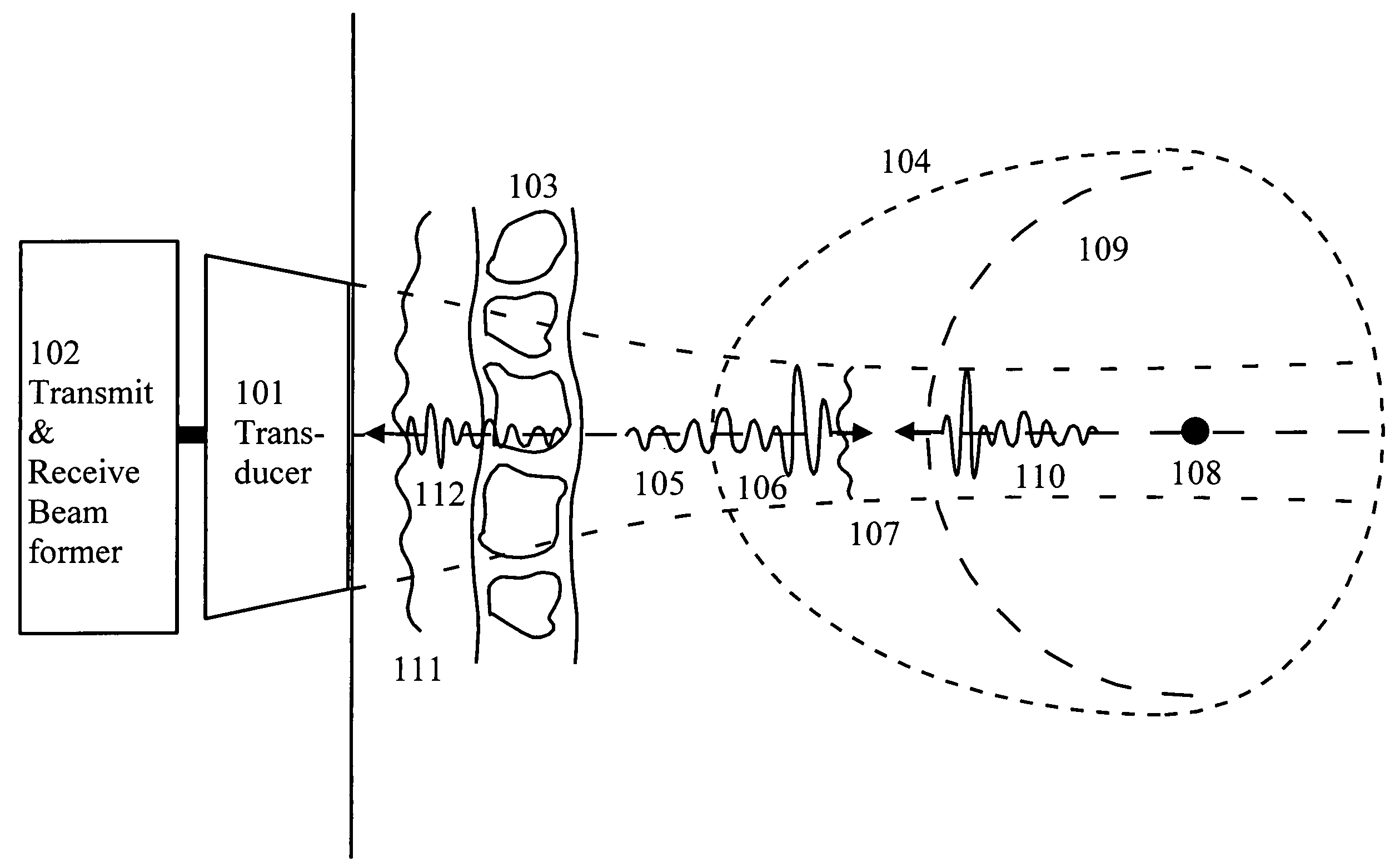
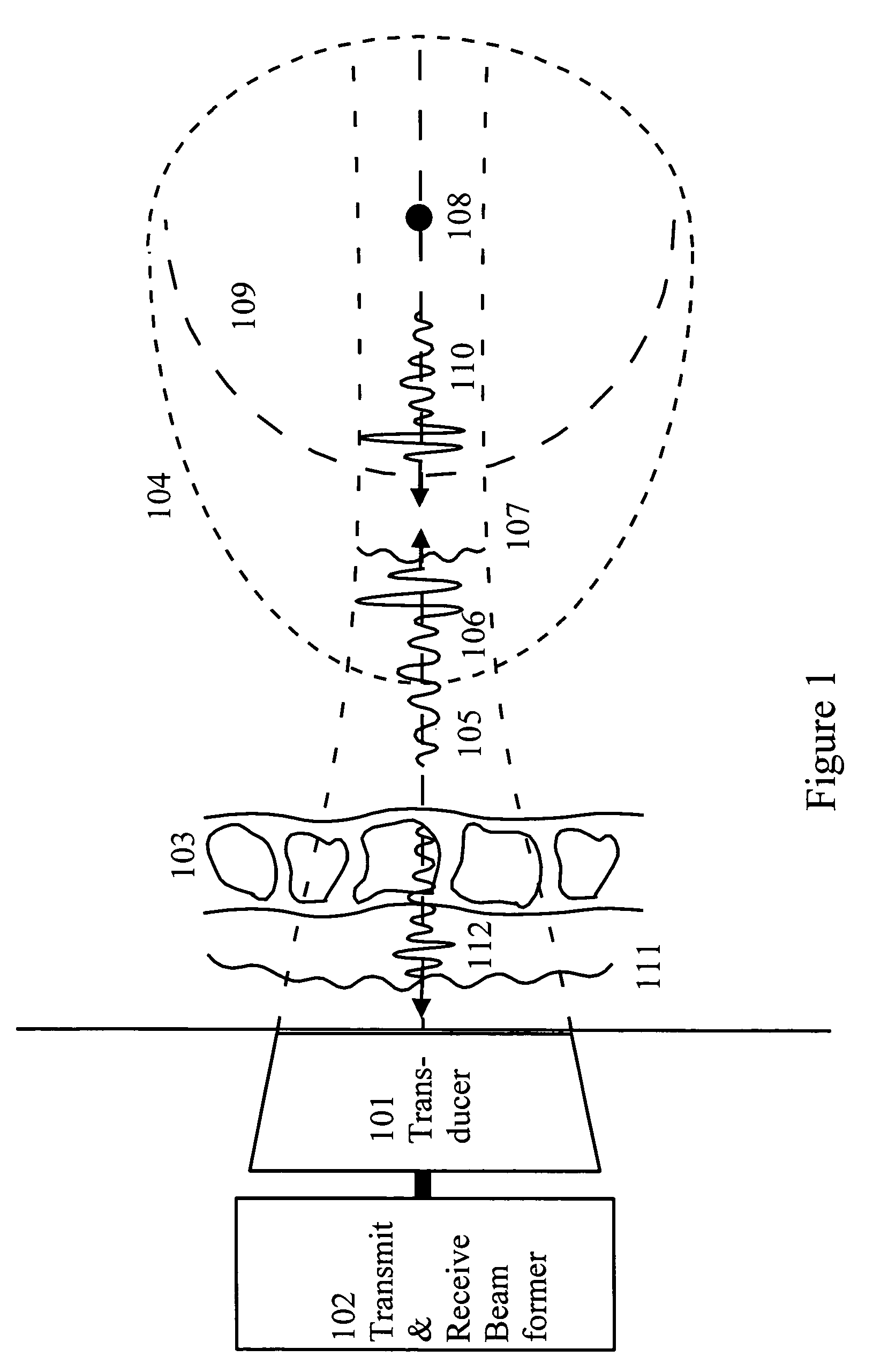
[0032]FIG. 1 shows a typical measurement situation where an ultrasound transducer array (101), driven by a transmit beam former (102), transmits a pulsed and focused ultrasound beam through the body wall (103) towards an object (104) to be imaged. The body wall is a heterogeneous mixture of fat, muscles, and connective tissue with differences in acoustic velocity and characteristic impedance. Multiple reflections within the body wall, and between structures in the body wall and the transducer, produce a reverberation tail (105) to the transmitted pulse (106) as it passes the wall. Similarly, the variations in the acoustic velocity produce aberration of the wavefront (107) as the pulse passes the wall.

[0033]When the pulse is reflected by a point scatterer (108) within the object, a wave with spherical wavefront (109) is produced. The relationship between the forward propagating transmit-pulse and the scattered pulse is well described by a second-order tem...


PUM


Abstract

An estimation method for correction filters for wavefront aberration correction in ultrasound imaging is given. The aberration is introduced due to spatial variations of the ultrasound propagation velocity in heterogeneous tissue. The correction filters are found as eigenvectors of the cross-correlation matrix of the element signals. In particular, the eigenvectors with a small spatial linear / plane phase component is sought. Detailed methods for calculating the eigenvectors are given.

Description

CROSS REFERENCE TO RELATED APPLICATION[0001]This application claims priority based on U.S. Patent Provisional Application No. 60 / 487,903 filed Jul. 17, 2003.BACKGROUND OF THE INVENTION[0002]1. Field of the Invention[0003]The present invention is directed at methods for estimating corrections to reduce the impact which tissue induced wavefront aberration has on the quality of medical ultrasound images. The method hence has applications to all situations were ultrasound imaging is used in medicine, but also other areas where ultrasound imaging is applied.[0004]2. Description of the Related Art[0005]Spatial variations in the acoustic properties (mass density and compressibility) are the basis for ultrasound backscatter imaging of tissue. However, large variations combined with complex tissue structures, degrade the images because of the following effects:[0006]i) Interfaces between materials with large differences in acoustic properties can give rise to multiple reflections of the ultr...

Claims


Application Information

Patent Timeline
Patent Type & Authority Patents(United States)
IPC IPC(8): A61B8/00G01S7/52G01S7/521
CPCG01S7/52038G01S7/52049G01S7/52079
Inventor ANGELSEN, BJORN A. J.JOHANSEN, TONNI F.VARSLOT, TROND KARSTEN
Owner ANGELSEN BJORN A J
Why Eureka
Try Eureka