Temperature compensation device and method for a voltage regulator

a voltage regulator and temperature compensation technology, applied in the direction of electric variable regulation, process and machine control, instruments, etc., can solve the problems of inability to compensate the current sense signal ix accurately, the resistors with negative temperature coefficients are not ordinary resistors, and therefore are more expensive, so as to avoid noise interference

Active Publication Date: 2007-09-25
RICHTEK TECH
View PDF1 Cites 22 Cited by
  • Summary
  • Abstract
  • Description
  • Claims
  • Application Information

AI Technical Summary

Benefits of technology

[0008]Yet another object of the present invention is to provide a temperature compensation device and method without lengthened conductive wire to avoid noise interferences.

Problems solved by technology

Unfortunately, the resistance of an ordinary resistor is a function of temperature, so that the load line is also the function of temperature.
Consequently, incorrect operations may happen because the control circuit 102 provides incorrect PWM signal due to the incorrect current sense signal Ix caused by the temperature coefficient of the current sense resistor Rs.
Nevertheless, resistors with negative temperature coefficients are not ordinary resistors and thereby are more expensive.
Moreover, there is always a distance between the resistors RADJ and Rs, and hence the temperature changes in the resistors RADJ and Rs are different, thereby introducing inaccurate compensation to the current sense signal Ix.

Method used


Image

  • Temperature compensation device and method for a voltage regulator
  • Temperature compensation device and method for a voltage regulator
  • Temperature compensation device and method for a voltage regulator

Examples


Embodiment Construction

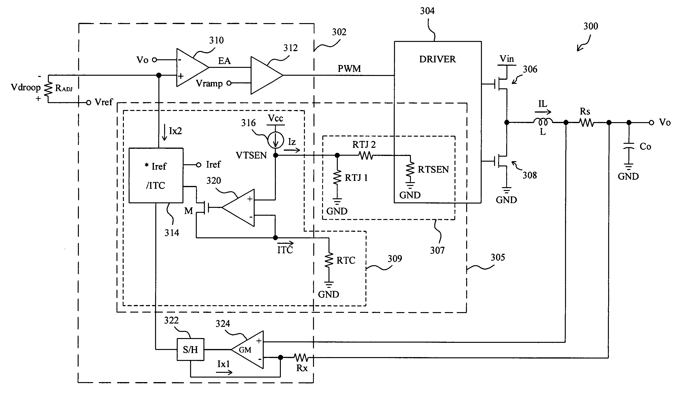
[0018]According to the present invention, FIG. 3 schematically shows a voltage regulator 300, in which control circuit 302 comprises error amplifier 310 in response to the output voltage Vo of the regulator 300 and reference voltage Vref to produce error signal EA for PWM comparator 312 to compare with ramp signal Vramp to thereby generate PWM signal, and with the PWM signal driver 304 switches transistors 306 and 308 coupled in series between input voltage Vin and ground GND to produce inductor current IL flowing through inductor L to charge output capacitor Co to generate the output voltage Vo. According to the voltage drop across current sense resistor Rs that is coupled to the inductor L, transconductive amplifier 324, serving as current sense circuit, generates current sense signal Ix1 supplied to temperature compensation device 305 via sample-and-hold circuit 322. Owing to the current sense resistor Rs having temperature coefficient TC1, the current sense signal Ix1 will be af...


PUM


Abstract

In a voltage regulator including an inductor current flowing through a sense element with a first temperature coefficient, and a current sense circuit for generating a current sense signal related to the first temperature coefficient by sensing the inductor current from the sense element, a temperature compensation device and method determines a second temperature coefficient according to the first temperature coefficient and temperature variation, and produces a compensation signal with the second temperature coefficient to compensate variations in the current sense signal caused by the first temperature coefficient.

Description

FIELD OF THE INVENTION[0001]The present invention is related generally to a voltage regulator, and more particularly, to a temperature compensation device and method for a voltage regulator.BACKGROUND OF THE INVENTION[0002]Voltage regulators have been applied extensively in various electronic products as power supplies. In state-of-art voltage regulators, in order to prevent load from being damaged due to voltage spike of the output in transients, voltage droop function is adapted for diminishing the voltage spike on the load in transients. FIG. 1 schematically shows a conventional voltage regulator 100 with voltage droop function, in which driver 104 switches transistors 106 and 108 coupled in series between input voltage Vin and ground GND in response to pulse width modulation (PWM) signal provided by control circuit 102. Thereby, inductor current IL is generated to charge output capacitor Co so that output voltage Vo is produced. In the control circuit 102, from the voltage drop ...

Claims


Application Information

Patent Timeline
Patent Type & Authority Patents(United States)
IPC IPC(8): G05F1/613
CPCH02M3/156H02M2001/0009Y10S323/907H02M1/0009
Inventor WANG, HUNG-ICHEN, JIUN-CHIANG
Owner RICHTEK TECH
Why Eureka
Try Eureka