Rotor and gyrocopter with said rotor

a rotor and gyrocopter technology, applied in the direction of liquid fuel engines, marine propulsion, vessel construction, etc., can solve the problems of large stress on the blade connector, the blade neck, and the difficulty of reducing the flapping hinge distance or reducing it below a specific value, so as to improve the flying comfort, the effect of improving the flying properties and ensuring the safety and reliability

Inactive Publication Date: 2007-10-02
AIRBUS HELICOPTERS DEUT GMBH
View PDF8 Cites 15 Cited by
  • Summary
  • Abstract
  • Description
  • Claims
  • Application Information

AI Technical Summary

Benefits of technology

[0008]An object and a technical problem on which the invention is based is that of creating a rotor for a rotorcraft, which rotor ensures improved flying properties, greater flying comfort, and greater safety and reliability, and is also suitable in at least one embodiment as a tilting rotor for a tiltrotor rotorcraft. A rotorcraft having such a rotor is also to be made available.
[0012]The manner of achieving the object of the present invention allows the provision of a rotor, in particular a so-called hingeless and bearingless rotor, in which the rotor blade or blades can be connected to the rotor head or rotor mast in flexurally soft fashion and with a small virtual flapping hinge distance that is considerably reduced as compared with previously known bearingless rotors. It is possible as a result to improve the flying properties of a rotorcraft equipped with such a rotor, and considerably to increase flying comfort.
[0013]The rotor according to the present invention furthermore exhibits less vibration than conventional bearingless rotors, which in turn has a positive effect on the flying properties and comfort of the rotorcraft and reduces loads on the blade connector and blade neck of a particular rotor blade. It is therefore not necessary to make the dimensions of the blade-connector region of the rotor blade as large as in the case of a conventional bearingless rotor blade, since the forces and moments that occur can be transferred more advantageously and more favorably. The weight of the rotor blade, and hence in turn the total weight of the rotor, can consequently be reduced.
[0014]The two auxiliary flapping hinges, which, as will be explained in even further detail below, can also perform load-discharging functions and thereby ensure redundancy, furthermore greatly reduce the probability of malfunction and failure in the rotor according to the present invention. A fail-safe design can thus be implemented for the rotor. Despite the small flapping hinge distance, the rotor according to the present invention possesses excellent durability and service life. In contrast to the existing art, moreover, a separate disconnect point between the blade connector and the rotor blade is not necessary. The rotor concept according to the present invention can be implemented for rotors having one or more rotor blades and an even or odd number of rotor blades.
[0015]Because it can be embodied both with a small flapping hinge distance and, if necessary, with very lead-lag-stiff rotor blades, the rotor according to the present invention is very advantageous in particular for tiltrotor rotorcraft. This is because in a tilting rotor, the virtual flapping hinge must be disposed as centrally as possible, i.e. the flapping hinge distance should ideally be 0%. This requirement can be entirely met by the rotor according to the present invention. Only in this fashion can the lead-lag deformations that otherwise occur upon flapping of the rotor blade as a result of Coriolis forces be avoided. With a lead-lag-stiff rotor design and undiminished Coriolis forces, on the other hand, it might become impossible to guarantee rotor strength.

Problems solved by technology

This relative high natural flapping frequency, and the vibrations that result therefrom in the bearingless rotor, are disadvantageous in terms of the helicopters flying characteristics, and lead to large stresses on blade connector 144 and blade neck 146.
Because of the large stresses on the rotor blade in a bearingless rotor, and the strength of those components that must therefore be ensured, it is extremely difficult to reduce the flapping hinge distance or decrease it below a specific value.
In conventional bearingless rotors, a small flapping hinge distance would considerably reduce the durability and service life of the rotor blade in question, which of course is disadvantageous or even hazardous.

Method used


Image

  • Rotor and gyrocopter with said rotor
  • Rotor and gyrocopter with said rotor
  • Rotor and gyrocopter with said rotor

Examples


first embodiment

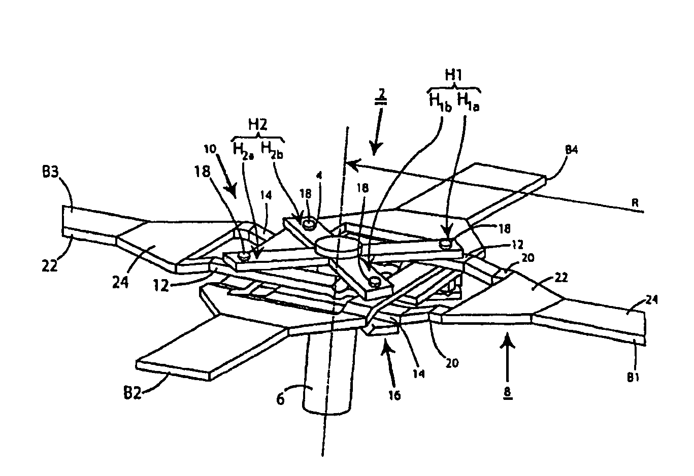
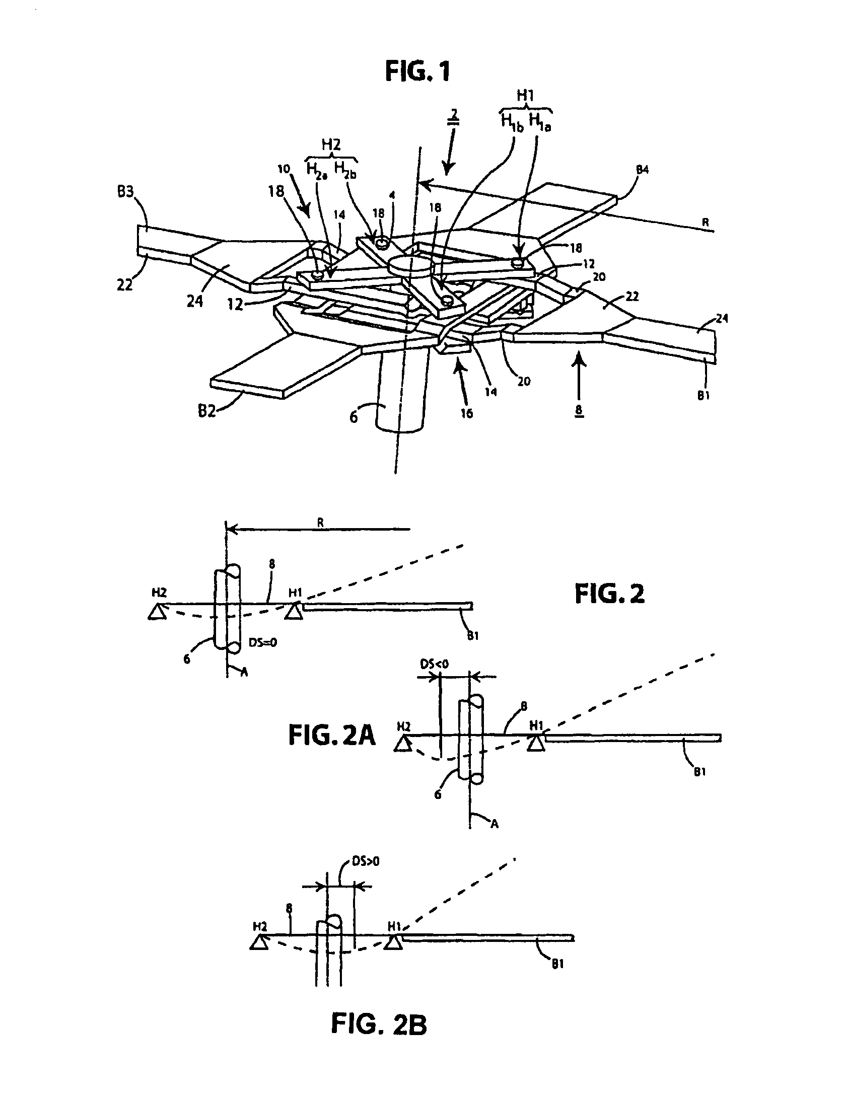
[0038]FIG. 1 is a schematic perspective plan view of a hingeless rotor according to the present invention in accordance with a The rotor encompasses a rotor head 2 having a plate-shaped, four-armed rotor star 4, flexurally soft in the flapwise direction, that engages nonrotatably on a rotor mast 6 and serves as a torque-transmission element, as well as four similarly configured rotor blades B1, B2, B3, B4. For the sake of clarity, the lift-generating regions of the rotor blades are not depicted in the drawing. The rotor blades are fabricated substantially from fiber composite material. Each two rotor blades B1, B3; B2, B4 that constitute a rotor blade pair are located at a 180-degree offset from one another. The two rotor blade pairs thus formed are in turn disposed at a 90-degree offset from one another. Each rotor blade possesses, for example, a blade neck 8 having flexurally soft, flexurally elastic blade-neck portions. Rotor blades B1, B2, B3, B4 are connected, in the region of...

second embodiment

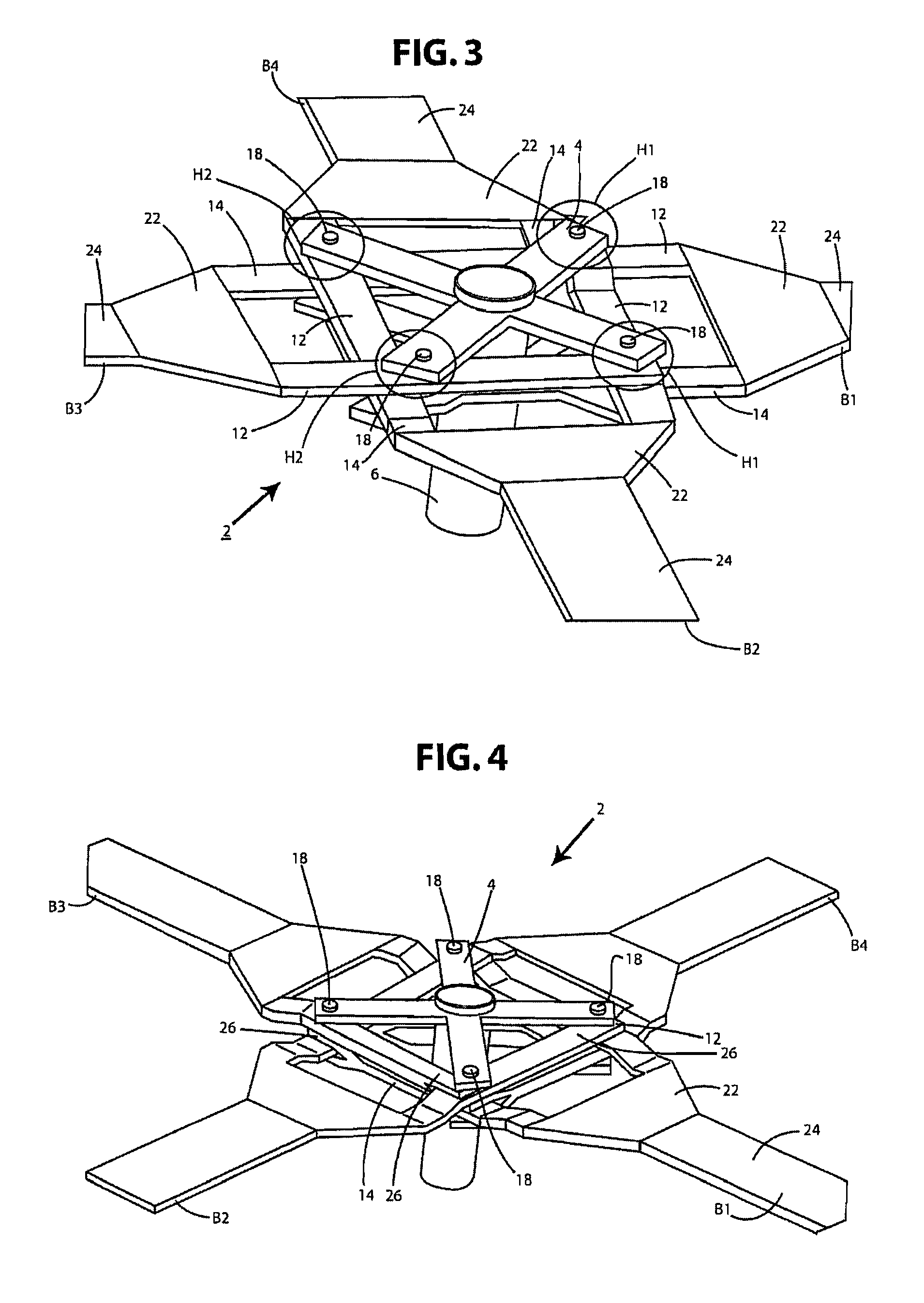
[0056]In principle, however, the two connector arms 12, 14 of a respective rotor blade B1, B2, B3, B4 can also lie in a common plane, or in a common plane with the base portion and the strip-shaped blade-neck region. An embodiment of this kind is shown in FIG. 3, which is a schematic, perspective plan view of a rotor according to the present invention in accordance with a Here, for each rotor blade B1, B2, B3, B4, the free end of one connector arm 12, 14 is bent or stepped upward, and that of the other one downward.

third embodiment

[0057]FIG. 4 is a schematic, perspective plan view of a rotor according to the present invention in accordance with a This variant is largely similar to that of FIG. 1, but the free ends of connector arms 12, 14 of a rotor blade B1, B2, B3, B4 are each embodied in the form of a fork terminal 26. With the rotor in the assembled state, fork terminal 26 is located in the region of an auxiliary flapping hinge H1, H2 and is joined to a strip-shaped region, located in the vicinity of base portion 22, of a connector arm 12, 14 of a respectively adjacent rotor blade. Fork terminals 26 make it possible to achieve greater retention strength in the joining points located at auxiliary flapping hinges H1, H2, and easier positionability during the assembly of rotor blades B1, B2, B3, B4.


PUM


Abstract

A rotor, comprising at least one rotor blade connectable to a rotor head, which rotor blade possesses a blade neck having a virtual flapping hinge in the form of a flexurally soft, flexurally elastic blade-neck portion, there being provided, in a blade-connector region of the blade neck, two auxiliary flapping hinges, spaced apart from one another in the radial longitudinal direction of the rotor blade with reference to a rotor radius, between which the virtual flapping hinge is substantially disposed and between which the blade neck is deformable in flexurally elastic and curved fashion in the context of a flapwise motion. A rotorcraft, in particular a helicopter, in particular a tiltrotor helicopter, having at least one such rotor.

Description

[0001]The present invention relates to a rotor and to a rotorcraft, in particular a helicopter, having such a rotor.BACKGROUND[0002]The lift-generating rotor blades of a rotor for a rotorcraft, in particular a helicopter, are deflected in various directions during continuous rotor operation, in particular by flapwise and lead-lag motions, and heavily stressed as a result. Rotor blades nowadays are manufactured predominantly from fiber composite materials.[0003]In a bearingless rotor according to the existing art, as shown in FIG. 14, bearingless rotor blades are mounted on the rotor head usually via a rotor-head plate. The rotor-head plate has rotor-head-side blade connectors, embodied in accordance with the number of rotor blades, that are each joined to a structural element of a rotor blade. This structural element 142 is embodied, at a radially inner (with reference to the rotor disc) end of the rotor blade, i.e. the end facing toward the rotor head, with a rotor-head-side blade ...

Claims


Application Information

Patent Timeline
Patent Type & Authority Patents(United States)
IPC IPC(8): B64C27/39B64C27/32B64C27/33
CPCB64C27/33B64C27/32
Inventor BECKER, GEROLDPFALLER, RUPERT
Owner AIRBUS HELICOPTERS DEUT GMBH
Why Eureka
Try Eureka