Methods of fabricating an addressable array of biopolymer probes

a biopolymer and array technology, applied in the field of arrays, can solve the problems of increasing cost, variance in position parameters, and small dna quantity available for arrays, and achieve the effect of not being overly costly

Inactive Publication Date: 2007-10-02
AGILENT TECH INC
View PDF29 Cites 59 Cited by
  • Summary
  • Abstract
  • Description
  • Claims
  • Application Information

AI Technical Summary

Benefits of technology

[0016]The present invention then, including methods, apparatus, and computer program products thereof, can provide any one or more, of a number of useful benefits. For example, arrays can be fabricated with an actual array pattern which is close to the target array pattern. Further, the invention is relatively reliable and not overly costly.

Problems solved by technology

In array fabrication, the quantities of DNA available for the array are usually very small and expensive.
While such variances can be reduced by constructing a dispensing apparatus with components of higher tolerance (that is, less variation), this can increase cost.
For example, thermal expansion or of components or slight displacement of them from their original positions over long periods of operation, leads to variance in position parameters.
These effects result in use of the target drive pattern not producing the target array on the substrate.
Such discrepancy may include mislocation of features, or features not being of the correct size.

Method used


Image

  • Methods of fabricating an addressable array of biopolymer probes
  • Methods of fabricating an addressable array of biopolymer probes
  • Methods of fabricating an addressable array of biopolymer probes

Examples


Embodiment Construction

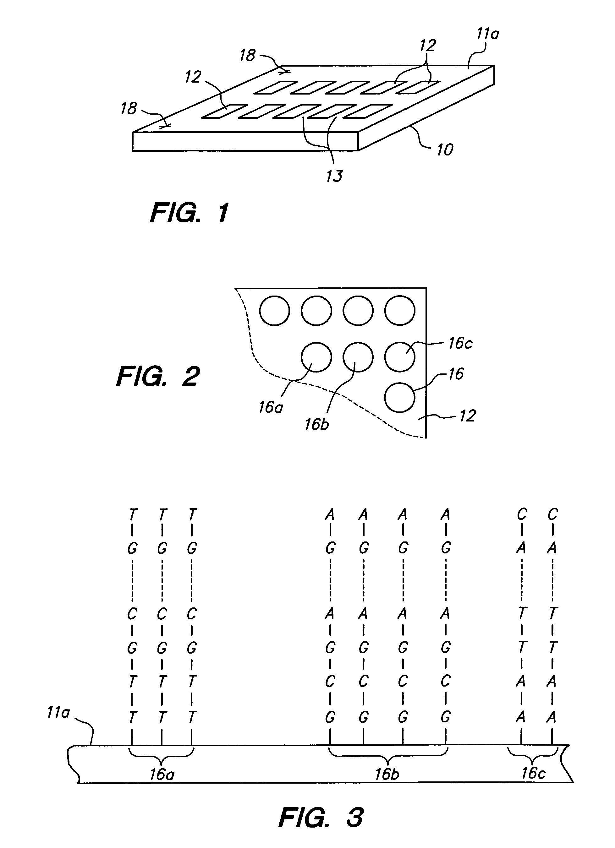
[0024]In the present application, unless a contrary intention appears, the following terms refer to the indicated characteristics. A “biopolymer” is a polymer of one or more types of repeating units. Biopolymers are found in biological systems and particularly include peptides or polynucleotides, as well as such compounds composed of or containing amino acid or nucleotide analogs or non-nucleotide groups. This includes polynucleotides in which the conventional backbone has been replaced with a non-naturally occurring or synthetic backbone, and nucleic acids in which one or more of the conventional bases has been replaced with a synthetic base capable of participating in Watson-Crick type hydrogen bonding interactions. Polynucleotides include single or multiple stranded configurations, where one or more of the strands may or may not be completely aligned with another. A “nucleotide” refers to a subunit of a nucleic acid and has a phosphate group, a 5 carbon sugar and a nitrogen conta...


PUM

PropertyMeasurementUnit
velocityaaaaaaaaaa
velocityaaaaaaaaaa
velocityaaaaaaaaaa

Abstract

A method of fabricating an addressable array of biopolymer probes on a substrate according to a target array pattern using a deposition apparatus, and a deposition apparatus which can execute the method and computer program products for the apparatus. The deposition apparatus which, when operated according to a target drive pattern based on nominal operating parameters of the apparatus, provides the probes on the substrate in the target array pattern. The method includes examining at least one operating parameter for an error from a nominal value which error will result in use of the target drive pattern producing a discrepancy between the target array pattern and an actual array pattern deposited. When an error is detected deriving, based on the error, a corrected drive pattern different from the target drive pattern such that use of the corrected drive pattern results in a reduced discrepancy between the target and actual array patterns.

Description

FIELD OF THE INVENTION[0001]This invention relates to arrays, particularly polynucleotide arrays such as DNA arrays, which are useful in diagnostic, screening, gene expression analysis, and other applications.BACKGROUND OF THE INVENTION[0002]Polynucleotide arrays (such as DNA or RNA arrays), are known and are used, for example, as diagnostic or screening tools. Such arrays include regions (sometimes referenced as features) of usually different sequence polynucleotides arranged in a predetermined configuration on a substrate. The arrays, when exposed to a sample, will exhibit an observed binding pattern. This binding pattern can be detected, for example, by labeling all polynucleotide targets (for example, DNA) in the sample with a suitable label (such as a fluorescent compound), and accurately observing the fluorescence pattern on the array. Assuming that the different sequence polynucleotides were correctly deposited in accordance with the predetermined configuration, then the obse...

Claims


Application Information

Patent Timeline
Patent Type & Authority Patents(United States)
IPC IPC(8): C12Q1/68C12M1/36G01N15/06B01L3/02B01J19/00C40B40/06C40B40/10C40B60/14C40B70/00G06T7/00
CPCB01J19/0046G06T7/0012B82Y30/00B01J2219/0036B01J2219/00378B01J2219/00527B01J2219/00529B01J2219/0054B01J2219/00585B01J2219/00596B01J2219/00605B01J2219/00608B01J2219/0061B01J2219/00612B01J2219/00626B01J2219/00637B01J2219/00659B01J2219/00677B01J2219/00689B01J2219/00693B01J2219/00695B01J2219/00702B01J2219/00722B01J2219/00725B01L3/0241C40B40/06C40B40/10C40B60/14C40B70/00B01J2219/00315
Inventor WEBB, PETER G.CAREN, MICHAEL P.SCHLEIFER, KYLE J.BASS, JAY K.
Owner AGILENT TECH INC
Why Eureka
Try Eureka